Assembly Guide
7
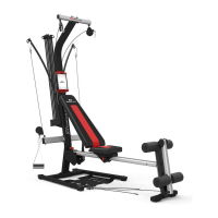
Step 3: Attach the Lower Lat Tower to the Base Frame
Assembly
Locate the following items:
• Lower Lat Tower Assembly (from Step 2)
• Base Frame Assembly (from Step 1)
• (2) 3/8" X 3/4" Button Head Screws (Item #B)
• (2) 3/8" Washers (Item #K)
Place the Base Frame Assembly on the floor, wide end facing you.
Center the Lower Lat Tower Assembly (Rod Box facing away
from you) over the Frame Assembly as shown in Figure C.
Place the bottom of the Lower Lat Tower onto the Rear Cross
Member.
Place (2) 3/8" Washers (K) over the end of (2) 3/8" X 3/4" Button
Head Screws (B) - one washer per screw. Lo o s e ly secure the Low e r
Lat Tower to the Rear Cross Member with the screws and washers.
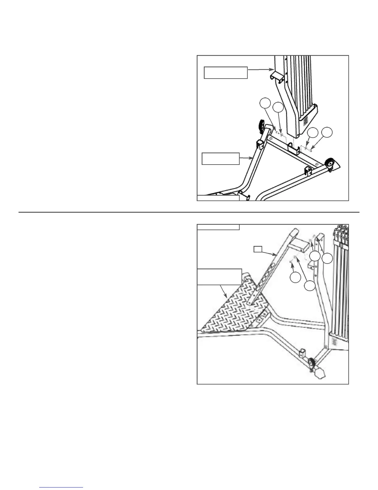
Step 4: Attach the Seat Support Rail to the Lat Tower
Locate the following items:
• Base Frame Assembly with Lower Lat Tower Assembly
(from Step 3)
• Seat Support Rail (Item #12)
• (2) 3/8" X 3/4" Button Head Screws (Item #B)
• (2) 3/8" Washers (Item #K)
Place the Base Frame with Lower Lat Tower Assembly (from Step
3) flat on the floor and place the Seat Support Rail (Item #12)
onto the connector on the Base Frame as shown in Figure D.
Gently push the Seat Support Rail onto the Lower Lat Tower con-
nector. Place (2) 3/8" Washers (K) over the end of (2) 3/8" X 3/4"
Button Head Screws (B) - one washer per screw. Loosely install
the screws with washers into the two side holes near the top of the
Seat Support Rail.
Figure C
K
B
Lower Lat
Tower Assembly
Base Frame
Assembly
B
K
Base Frame &
Lower Lat Tower
Assembly
Figure D
12
B
K
K
B
STOP! TAKE TIME NOWTO REVIEW AND TIGHTEN ALL INSTALLED HARDWARE!