MAINTENANCE
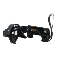
STUMP GRINDERS
REPLACING TEETH
When replacing the teeth the unit must be blocked securely off the ground to allow the
wheel to rotate.
The teeth should be inspected regularly (every 8 hours) for tightness and to ensure they
are not worn or that the carbide tip is not missing or chipped. Tighten and replace as neces-
sary.
Replacing Square Teeth:
1. With unit securely blocked off the ground and hydraulic couplers disconnected, remove
lock nuts on teeth being replaced.
2. Position new teeth and replace existing lock nut with new one provided.
3. Torquetospecication.(BoltTorqueSpecications)
Replacing Bolt-On Teeth:
1. With unit securely blocked off the ground and hydraulic couplers disconnected, remove
the two sockethead capscrews securing the tooth to the wheel.
2. Position the new tooth on one side while retaining the existing tooth on the other side
and secure in place with the existing sockethead capscrews.
NOTE: Be sure to maintain the existing tooth pattern when replacing any bolt-on teeth.
SeePartsDiagram
3. Torquetospecication.(BoltTorqueSpecications)
WARNING! Avoid serious injury. Lower the stump grinder to the ground, set the park-
ing brake, stop the skid steer engine and remove the key before leaving
the operator's seat. If unit must be left raised for maintenance block the
unit securely to prevent accidental release of the lifting mechanism. Dis-
connect the hydraulic couplers.
9776 7-29-14-3
REPLACING HYDRAULIC MOTOR
When replacing the hydraulic motor the unit should be either securely blocked up off the
ground or attached to a hoist with the hydraulic couplers disconnected.
NOTE: Field replacement of the internal motor seals voids warranty.
1. With unit securely positioned and hydraulic couplers disconnected, tag and disconnect
the hydraulic hoses from the hydraulic motor. Note the hose routing for re-installation.
2. Loosenthefoursocketheadcapscrewsonthecoupler.SeeFigure#1
3. Standard Flow: Slidethemotoroutofthecouplerandremovethetwo.50"capscrews
holdingthemotortothemotormountandremovethemotor.SeeFigure#1
High Flow:Removethefour.50"capscrewsholdingthemotortothemotormounts
andthenslidethemotoroutofthecoupler.SeeFigure#1