Do you have a question about the Bradco SG30 and is the answer not in the manual?
Primary responsibility for safety falls to the operator. Ensure trained individuals operate the equipment.
Symbol warns of possible injury. Read all warnings carefully for safety.
Use only manufacturer replacement parts. Record model and serial number for correct parts.
Signal word for serious injury or death if instructions are not followed.
Signal word for serious injury or death if instructions are not followed.
Signal word for minor injury if instructions are not followed.
Read all manuals and follow safety instructions before operation or maintenance.
Understand capabilities, dimensions, operations. Inspect before use.
Wear safety glasses, goggles, or face shield during operations causing debris.
Hydraulic fluid under pressure can penetrate skin. Seek medical attention if injected.
Avoid loose clothing. Work on level surface. Use correct tools. Wear protective equipment.
Operate only if trained. Keep controls clean. No riders. Operate from correct position.
Observe overhead and buried utility lines. Call local utilities before digging.
Hazardous dust can cause respiratory disease. Use dust suppression and PPE.
Hazardous fumes generated from paint. Work in ventilated area. Dispose of waste properly.
Be sure others know when and where you will be working. Never direct discharge towards people or property.
Stay clear of all moving parts.
Travel in safe transport position. Drive slowly over rough ground and slopes. Use safety lights.
Lower attachment, turn off engine, remove key, and apply brakes before maintenance.
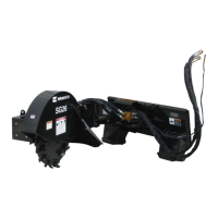
Diagram to acquaint with names of stump grinder components for manual reading and ordering parts.
Diagram shows decal locations. Use part numbers to order replacements. Read all decals.
Hazard warning for rotating blade, objects can be thrown. Stay back. Do not operate near bystanders.
Hazard warning for flying debris. Stay back. Objects can be thrown.
Hazard warning for high-pressure fluid. Relieve pressure before work. Wear PPE.
Warning that guard covers moving parts. Remove guard only for service.
Procedure for leaving operator's seat: Lower arms, disengage hydraulics, stop engine, remove key, engage brake.
Steps for installation: remove banding, existing attachment, install grinder, lower unit, install guard, connect hoses.
Steps for disconnecting: lower unit, stop engine, relieve pressure, disconnect hoses and harness, disconnect grinder from skid steer.
Stump grinder controlled by joystick and electrical valve assembly. Covers Paladin operating controls.
Explains operation of UP/DOWN/LEFT/RIGHT switches for frame movement and swing.
Steps for grinding stumps: check area, align grinder, position wheel, activate hydraulics, adjust cutting depth.
Check work area for utility lines before operating the stump grinder.
Continue cutting by swinging wheel left and right, lowering grinder. Reduce depth if wheel stalls.
Make shallow cuts for surface roots. Large chips can be thrown if cut is too deep.
Procedures for proper storage: clean unit, replace teeth, inspect for damage, tighten connections, check gearbox.
Follow regulations for transporting. Use extra care loading/unloading. Install SMV sign. Drive slowly.
Identified by decals. Lift at recommended points. Use capable accessories. Secure accessories.
Identified by decals. Secure to trailer at recommended points. Check stability before transport.
Lubricate parts with grease fittings every 8 hours. Clean fittings before use. Avoid excessive greasing.
Check oil level in gearbox weekly. Fill with 80-90 weight gear lubricant as necessary.
Lower grinder, set brake, stop engine, remove key before leaving seat. Block unit securely.
Inspect teeth regularly for tightness, wear, or missing carbide tips. Tighten and replace as needed.
Block unit or use hoist. Disconnect hydraulic couplers. Tag and disconnect hoses from motor.
Install new motor onto mount, position, retighten capscrews. Torque hardware. Reconnect hoses. Check for leaks.
Lower grinder, set brake, stop engine, remove key before leaving seat. Block unit securely.
Loosen capscrews on coupler. Slide motor out. Remove roll pin. Place new coupler on gearbox shaft.
Remove wheel guard, castle nut, cotter pin. Loosen capscrews on coupler. Remove motor.
Information for repairing or rebuilding a hydraulic cylinder. Keep work area clean. Protect cylinder rod.
Do not contact active surface of cylinder rod with vise. Rotate gland, pull rod, inspect piston and bore.
Steps for disassembling a threaded type gland: remove hex nut, piston, washer, and gland from rod.
Replace all seals. Install cylinder rod seal in gland. Use installation tool if available.
Do not contact the active surface of the cylinder rod with the vise to prevent damage.
Possible causes include hoses not hooked up, obstruction in lines, or valve not engaged. Solutions provided.
Causes: insufficient flow, damaged coupler, dirty filter, motor leakage, or gearbox failure. Solutions provided.
Causes: damaged line, O-rings, fittings, or seals. Solutions involve tightening or replacing parts.
Causes: low oil level, stalling, obstruction, dirty oil/filter, low relief valve. Solutions provided.
Causes: broken/missing teeth or bent gearbox shaft. Solutions: replace teeth or call service department.
Causes: faulty switch/connection, control valve coil, or spool. Solutions: repair or replace.
Table listing dimensions like width, height, length, depth, swing arc, lift, and number of teeth.
Torque values for SAE bolts based on grade, size, and thread type.
Torque values for metric bolts based on grade, size, and thread type.
Lists parts excluded from warranty, such as ground-engaging parts, cables, and teeth.
Defines the warranty period as 12 months from the commencement date or date of purchase.
List of parts for the stump grinder assembly, including item number, quantity, part number, and description.
List of parts for the rear guard assembly, including item number, quantity, part number, and description.
List of parts for the square tooth wheel assembly, including replacement tooth kit.
List of parts for the bolt-on tooth wheel assembly, including replacement tooth kit and tooth setup notes.
List of parts for the hydraulic valve assembly, including hoses, elbows, connectors, and the control valve itself.
List of replacement parts for the control valve, including cartridges and seal kits.
List of parts for the standard flow drive assembly, including motor, coupler, gearbox, and hoses.
List of parts for the high flow drive assembly, including motor, coupler, gearbox, and hoses.
Lists parts for standard flow hose kits, including female/male couplers, connectors, and hoses.
Lists parts for high flow hose kits, including female/male couplers, connectors, and hoses.
List of parts for cylinder assembly #100324, including seal kit details.
List of parts for cylinder assembly #101245, including seal kit details.
Diagram of the optional Electrical Control Box Assembly #104368 with Deutsch connector pin detail.
Diagram of wiring harness #108035, showing Deutsch connector pin detail and connections to the control valve.
Diagram of wiring harness #108036, showing Deutsch connector pin detail and connections to the control valve.