MAINTENANCE
STUMP GRINDERS
9778 7-29-14-3
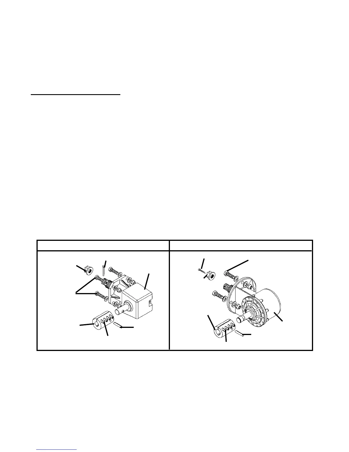
REPLACING GEARBOX
When replacing the gearbox the unit should be either securely blocked up off the ground
or attached to a hoist with the hydraulic couplers disconnected. NOTE: A new cotter pin
should be installed whenever the wheel has been removed.
1. With the wheel guard cover removed, remove the castle nut and cotter pin securing the
wheel to the gearbox.
2. Loosenthefoursocketheadcapscrewsonthecoupler.SeeFigure#1
3. Standard Flow: Slidethemotoroutofthecoupler.SeeFigure#1
High Flow:Removethefour.50"capscrewsholdingthemotortothemotormounts
andslidethemotoroutofthecoupler.SeeFigure#1
3. Removetherollpinholdingthecouplertothegearboxandremovethecoupler.See
Figure#2
4. Remove the four capscrews securing the gearbox to the stump grinder frame and re-
movethegearbox.SeeFigure#2 NOTE: Be prepared for the gearbox to drop
when the capscrews are removed.
5. Checklubricationlevelinthegearboxandaddasneeded.SeeSectionHInstallintothe
stump grinder frame using the existing hardware.
6. Place the new coupler on the gearbox shaft and reinstall the roll pin.
7. Reinstallthemotorintothecoupler(installthefour.50"capscrewsonhighowunits)
and retighten the sockethead capscrews.
8. Re-install the wheel using the new castle nut and cotter pin.
9. Re-install the wheel guard cover using the existing hardware.
10. Torqueallcapscrewstospecication.BoltTorqueSpecications
HIGH FLOW
ROLL PIN
GEARBOX
SOCKETHEAD CAPSCREWS
CASTLE
NUT
CASTLE
NUT
STANDARD FLOW
GEARBOX
COTTER PIN
FIGURE #2
ROLL PIN
SOCKETHEAD CAPSCREWS
COTTER PIN
COUPLER
CAPSCREWS SECURING
GEARBOX TO STUMP
GRINDER FRAME
COUPLER
CAPSCREWS
SECURING GEARBOX
TO STUMP GRINDER
FRAME
5. Reinstallthemotorintothecoupler(installthefour.50"capscrewsonhighowunits)
andretightenthesocketheadcapscrews.Torquetospecication.BoltTorqueSpecica-
tions