MAINTENANCE
STUMP GRINDERS
9777 7-29-14-3
4. Standard Flow: Install the new motor onto the motor mount using the existing hard-
ware.Slidethemotorwiththemountingplateintothecouplerwhilepositioningtherub-
ber bumpers and retighten the sockethead capscrews.
High Flow:Slidethemotorintothecouplerwhilemaintainingthepositioningofthe
motor mounting plates. Reinstall the motor onto the motor mountings using the existing
hardware and retighten the sockethead capscrews.
WARNING! Avoid serious injury. Lower the stump grinder to the ground, set the park-
ing brake, stop the skid steer engine and remove the key before leaving the
operator's seat. If unit must be left raised for maintenance block the unit
securely to prevent accidental release of the lifting mechanism. Disconnect
the hydraulic couplers.
REPLACING GEARBOX/MOTOR COUPLER
When replacing the coupler the unit should be either securely blocked up off the ground
or attached to a hoist with the hydraulic couplers disconnected.
1. With unit securely positioned and hydraulic couplers disconnected, loosen the four
sockethead capscrews on the coupler.
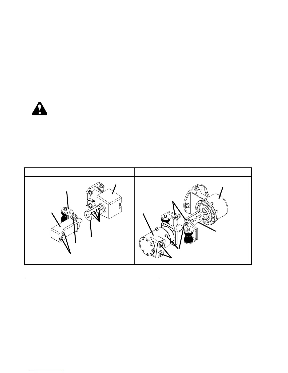
2. Standard Flow:Slidethemotoroutofthecoupler.SeeFigure#1
High Flow:Removethefour.50"capscrewsholdingthemotortothemotormounts
andslidethemotoroutofthecoupler.SeeFigure#1
3. Remove the roll pin holding the coupler to the gearbox.
4. Place the new coupler on the gearbox shaft and reinstall the roll pin.
HIGH FLOW
TAG HYDRAULIC HOSES
MOTOR
COUPLER
GEARBOX
SOCKETHEAD
CAPSCREWS
MOTOR
MOUNT
MOTOR
MOUNTS
.50" X 1.75" CAPSCREW
MOTOR
STANDARD FLOW
GEARBOX
TAG HYDRAULIC HOSES
FIGURE #1
5. Torqueallhardwaretospecication.SeeBoltTorqueSpecications
6. Re-connectthehydraulichosesandttingstothenewmotor.
7. Check for leaks and tighten as required.
.50" X 2.25" CAPSCREWS & NUTS