Automation Guide Process Flow and Wiring Tables
100-214-273 Rev. 1 37
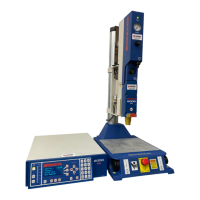
6.11.1 Wiring Table, Converter Stack, Standard Automation, Process Flow 11
#10 Process Flowchart 11
Install 100-246-1178
jumper box into J7
J3 User I/O connector on
power supply rear HD-44
Signal Name Pin # Colors Direction Signal Type Definition
1 User definable input 1 Wht/Blk Input 24V True Set:EXT SIGNAL
2 EXT_RESET 3 Grn/Blk Input 24V True System Reset
3 G_ALARM 6 Blk/Wht Output 0V True General Alarm
4 24V RETURN 12 Orn/Red 24V Return 24V Return
5 24V SOURCE 13 Blu/Red Output +24V Source +24V Source
6 READY 21 Blu/Blk/Wht Output 0V True Ready Output
7 24V RETURN 27 Blu/Wht/Orn 24V Return 24V Return
8 24V SOURCE 28 Blk/Wht/Orn +24V +24V Source
9 PB RELEASE 34 Red/Wht/Grn Output 0V True PB Release
10 24V RETURN 41 Grn/Orn/Red 24V Return 24V Return
11 24V SOURCE 42 Orn/Red/Blu +24V +24V Source
All voltages shown in this manual are direct current (DC) unless otherwise noted