6.
The total
indicator reading
in
position no. 1
(after
the
gib
is set) should
equal the total
indicator
reading in
position no. 2
within
i .0002",
if
not,
remove and
scrape
the
gib and
repeat the setting.
7. Check
lost motion
as
per
Section 7.9.1
7.8.4
Knee
to
Column
Gib
Setting
1. Remove
the
way
wiper
cover
(3005096)
and
wiper
(3005099)
to expose
the knee to column
gib.
2. Manually, using the crank
handle, raise
and
lower the knee and turn the
adjusting screw
(8005088)
until a smooth
movement is
attained.
7.9 LOST
MOTION AND BACKLASH
COMPENSATION
NOTE:
ln
serting
tbe
gib
stripS.
extrente,
cgre.must b'e
taken to ensure
tbat tbey
are not ooer-
tigbtered
o* i':r
*i
'
axis stdlls may occur; similarly
if tbe
grb
sffips
are
left too
slack,lostntolit:,,,
-
)ot
sE
Jnce
j;.:'ish
andpoorrepeatability
may result.
Itis essential
tberefore tbat, wben adjusting tbe
gib
stips, tbe
correct
procedure
is
followed,
and
lost motion is checked to ensure tbat tbe optimam settingbas
been
acbieoed. Lost
rnotion
should
be less tban .025 mm
(.001");
if tbis
fiyrt
is
exceeded,
slacken
the
gib
strtp btt one
quarter
of a rurn and recbeck.
It sbould also be noted
tbat lost motion
may
be
promoted
if
an
inappropriate
slideway
lubicant is used.
7
.9.7
To
Check Lost
Motion
Pre-requisites
1. Gib
strips set as
perSection
7.8.1
,7
.8.2
or
7 .8.3 .
2. Zerc
backlash compensation
has
been
entered into
the
TNC software
parameters
39
f.or
X
axis or
40
for
Y
axis.
(Follow
procedure
as
per
Section
7.9.2,
but enter
zero).
Equipment
Dial
gauge
(reading
to
.002
mm or better and having a travel
greater
thalrr
2 mm), clock stand
with
magnetic base.
Measurement
procedure
1.
Apply knee locks.
2.
Move the
axis
to
be checked to
its
mid
position.
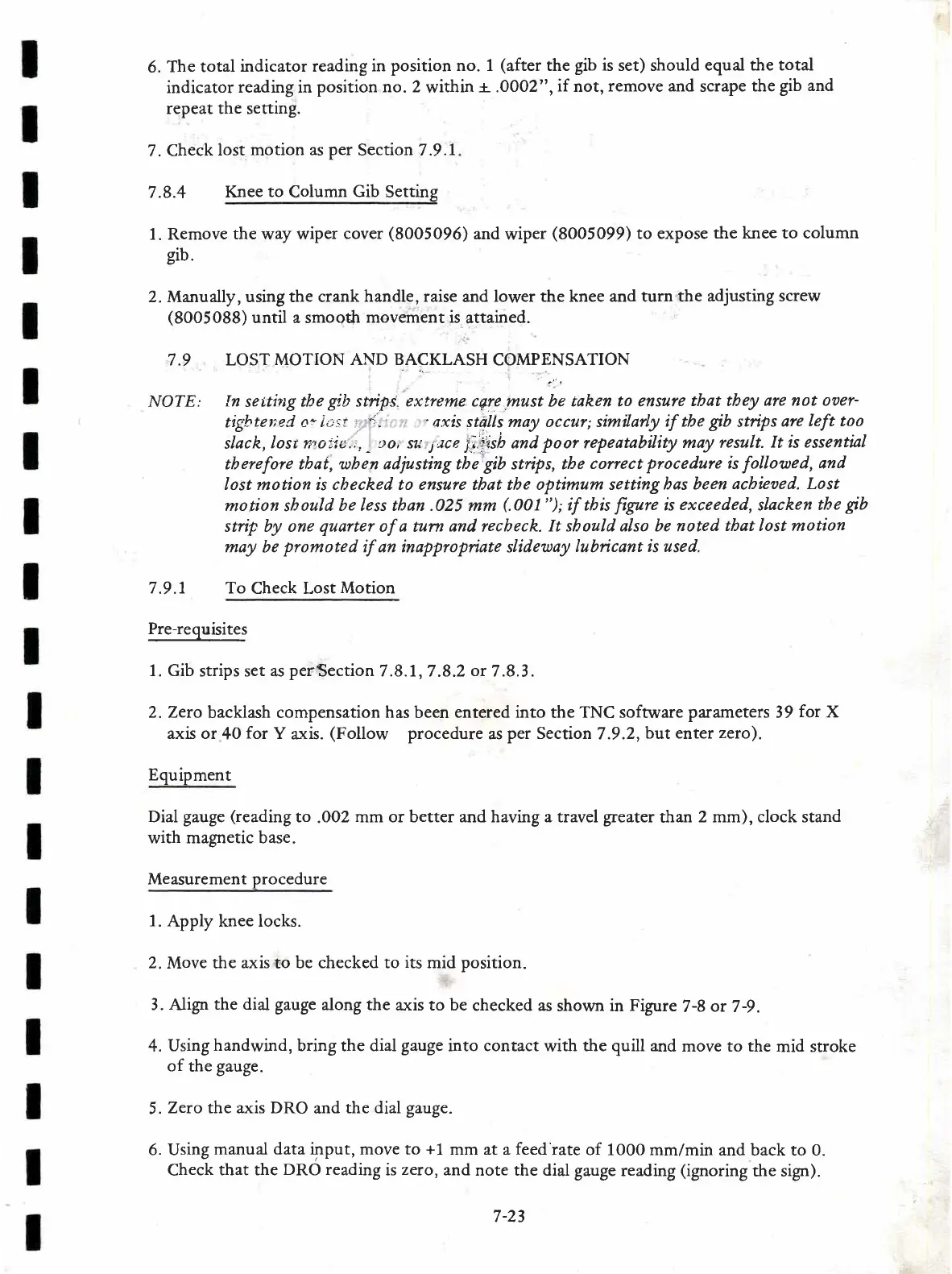
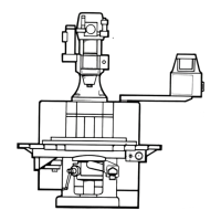
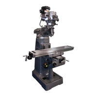
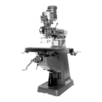
3. Atign
the dial gauge
along the
a^:<is to be
checked as
shown in
Figure
7-8
or
7-9.
4.
Using
handwind,
bring the dial
gauge
into contact
with
the quill and
move to the
mid stroke
of
the
gauge.
5.
Zero the axis DRO
and
the dial gauge.
6. Using
manual data input, move to
+1
mm at a
feed
rate
of 1000 mm/min
and back to 0.
Check
that the
DRO reading
is
zero,
and
note the dial gauge
reading
(ignoring
the sign).
7-23