SECTION
VIII
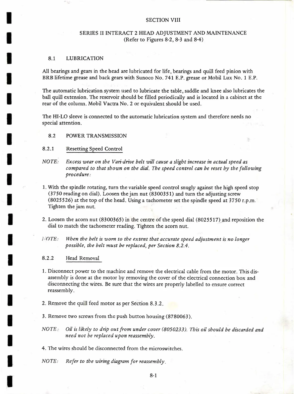
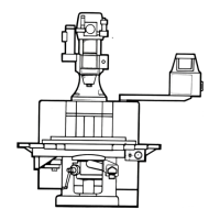
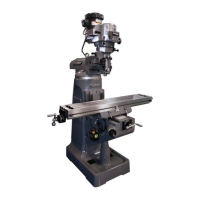
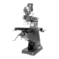
SERIES
II INTERACT 2 HEAD ADJUSTMENT
AND MAINTENANCE
(Refer
to
Figures
8-2,8-3 and 8-4)
8.1 LUBRICATION
All bearings and
gears
in the head are lubricated for
life,
bearings and
quill feed
pinion
with
BRB lifetime
grease
and back
gears
with Sunoco No.
741
E.P.
grease
or Mobil Lux
No.
1
E.P.
The automatic lubrication system
used
to lubricate the
table, saddle
and knee also
lubricates the
ball
quill extension.
The reservoir
should be
filled periodically
and is located in
a
cabinet
at the
rear of
the column. Mobil
Vactra
No. 2
or
equivalent
should
be used.
The HI-LO sleeve is connected to the
automatic lubrication system and therefore
needs no
special attention.
8.2
POWER
TRANSMISSION
8.2.7 Resetting
Speed Control
NOTE: Excess
uear
on
tbe Vari-drioe belt will cause
a sligbt increase
in acrual speed as
compared
to tbdt
sbown on tbe
dial.
Tbe
speed
control can be
reset
b)/ tbe
follouing
procedure:
1.
With
the
spindle
rotating,
turn
the variable
speed
control
snugly against the high speed stop
(3750
readingon
dial).
Loosen the
jam
nut
(8300351)
and
turn
the adjusting screw
(8025526)
at the top of
the head.
Using a tachometer set the spindle
speed
at
3750
r.p.m.
Tighten
the
jam
nut.
2.
Loosen the
acorn nut
(8300365)
in the centre
of
the
speed
dial
(8025517)
a;nd
reposition
the
dial
to match the
tachometer reading. Tighten the
acorn nur.
|';OTE: Wben
tbe belt is worn to the
e?ctent
tbat accurate
speed adjustment is no longer
possible,
tbe belt
must
be replaced,
per
Section 8.2.4.
8.2.2 Head
Removal
1. Disconnect
power
to the
machine and remove the electrical
cable from
the motor. This
dis-
assembly
is
done
at
the
motor
by removing
the cover of
the
electrical
connecrion box and
disconnecting
the
wires.
Be sure that the
wires are properly
labelled
to ensure
correct
reassembly.
2. Remove the quill
feed
motor as per
Section
8.3.2
3.
Remove two
screws
from
the push
button housing
(3730063).
NOTE
Oil is likely to dip out
from
under coaer
(8050233).
Tbis
oil sbould
be discarded
and
need
not
be
replaced
upon reassembly.
4.
The
wires
should be disconnected
from
the
microswitches.
NOTE:
Refer
to tbe wiring diagram
for
reassembly
8-1