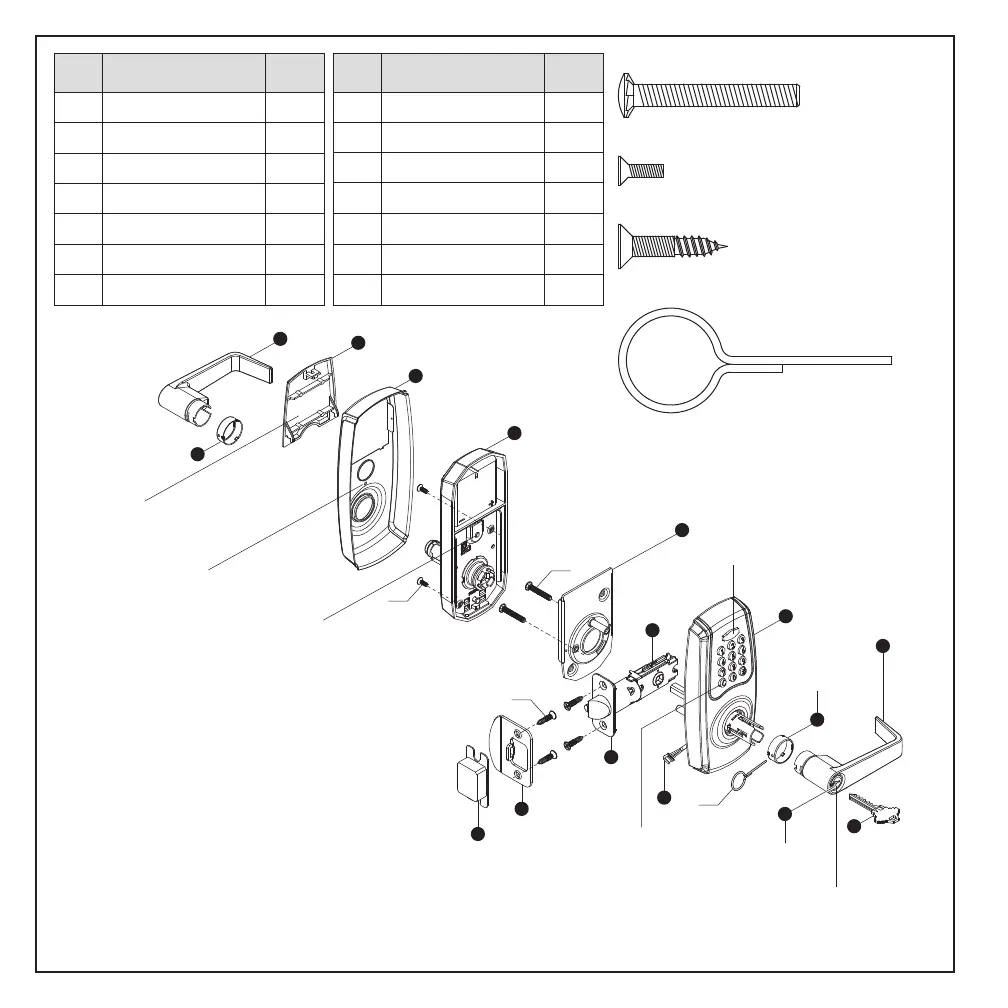
E
Latch
1
F
1
G
Mounting Plate
1
A Key
B Cylinder
C Exterior Assembly
D Power Cable
1
2
1
1
Part Description
Quantity
Interior Assembly
H
I
Battery Cover
Decorative Cover
1
J
Lever
1
K
L
M
N
Strike Plate
Dust Box
2
1
Collar
Round Corner Faceplate
1
1
2
Part Description
Quantity
See Note 1
See Note 1 & Note 2
Note 1: Cylinder (B) and collar (N) are pre-installed in the exterior lever (J).
Note 2: Collar (N) is pre-installed on interior lever (J).
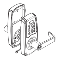
INTERIOR TURN SWITCH
1. It is auto-locked when the turn switch is vertical.
2. Lockset is set to passage mode when turn
switch is horizontal.
3. The turn switch must be in horizontal position to
enter programming mode. Exit Programming
mode by rotating the switch to vertical position.
INDICATORS
1. Red light: Represents an incorrect entry
or the unit is in programming mode.
2. Yellow light: Flashes when the batteries
are low in power.
3. Green light: Represents a correct entry.
CLEAR BUTTON
1. When there is an input error, use
©
button to clear all input typos.
N
L
C
F
J
H
I
BB
EE
DD
T1
E
M
K
BATTERY COVER
1. Protects the batteries from
unexpected damage.
INTERIOR INDICATOR LIGHT
1. Flashes when the batteries are low in power.
MECHANICAL CYLINDER OVERRIDE
1. To unlock the lockset by a valid key.
A
G
B
N
D
J
BB — 1-1/4" (32mm) Mounting Plate Screws [Qty: 2]
DD — 5/16" (8mm) Battery Compartment Screws [Qty: 2]
EE — 3/4" (19mm) Latch & Strike Plate Screws [Qty: 4]
T1 — Catch tool [Qty: 1]
For questions, call:
1-866-LOCK-PRO
(1-866-562-5776)
PAGE 2