Brivis 17 Evap AC IM
8. WATER CONNECTION
8.1 INLET CONNECTION
The water inlet connection point is under the cooler base on the left hand side, at the high side of the roof� The
connection is via a 1/2” BSP female tting supplied on a exible hose.
8.2 TANK WATER QUALITY MANAGEMENT.
The Brivis Advance, Brivis Promina and Brivis Contour's Series electronic water level sensor automatically maintains
the correct water level within the tank� The Brivis Advance and Brivis Promina Series models is programmed to
periodically ush the tank and rell it with clean water, depending on the operating conditions, and automatically
maintain the water quality within the tank. The Brivis Contour Series is tted with an AquaSave module that
maintains water purity during the cooler’s operation and therefore does not ush as often.
8.3 WATER DRAIN CONNECTION
Brivis Advance, Brivis Promina and Brivis Contour Series models
have a drainage connection point at the underside of the base, on
the low side of the roof�
Local jurisdictions may require a discharge pipe to be tted to the
drain outlet of evaporative coolers� Where the roof or catchment
area is used for the collection of potable water, the manufacturer
recommends that the outlet of the discharge pipe is separately
drained to avoid any contamination of water intended for potable
use�
If a discharge pipe is required, the manufacturer recommends that
the outlet is located such that water is adequately dispersed and
does not cause nuisance or damage, for example gutter overow
and accelerated corrosion�
Check requirements with your local jurisdiction�
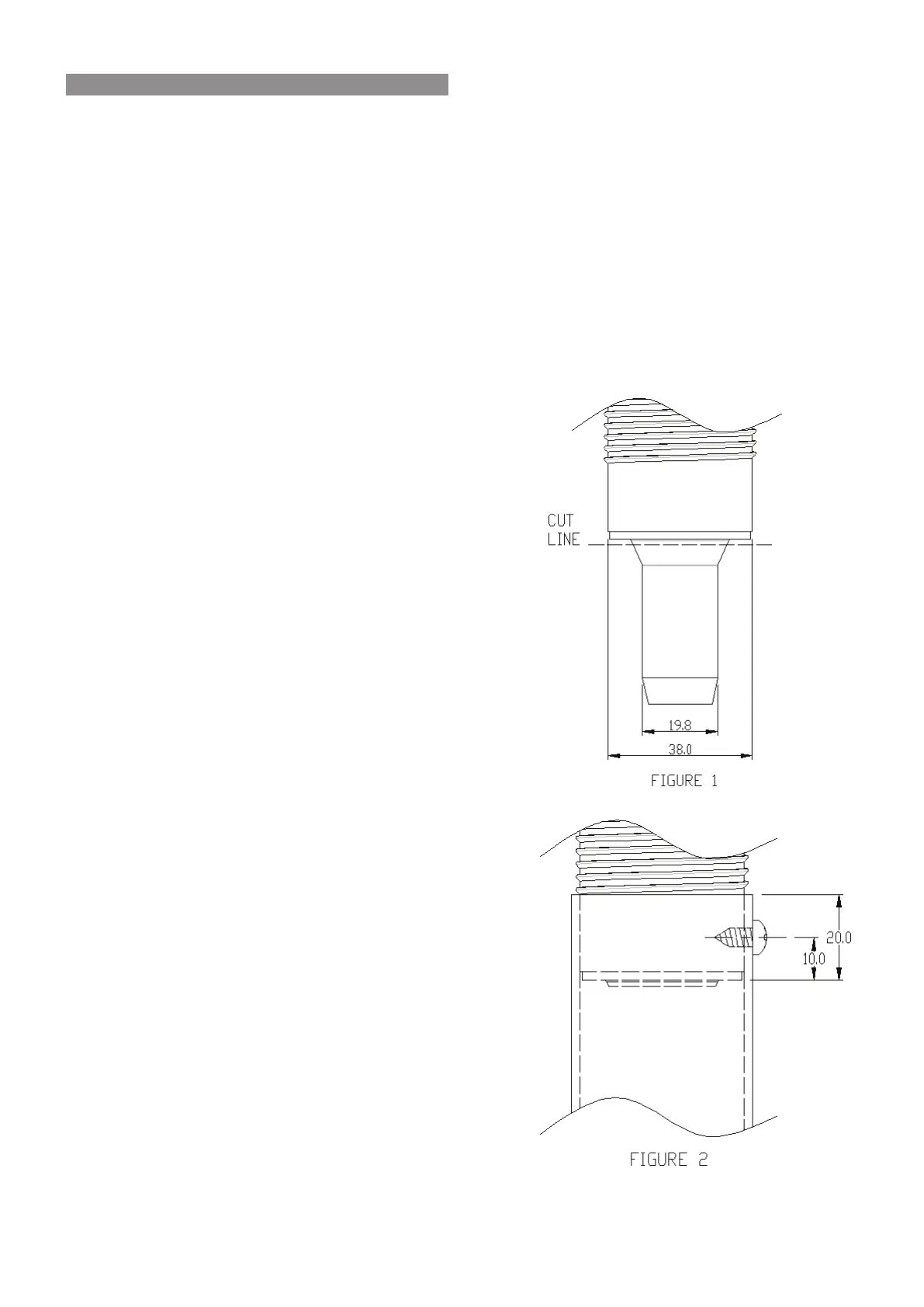
There are two recommended options when connecting
drainage to the unit:
•
Option one is for a small diameter pipe to be tted over the
ø19�8mm spigot detailed in Figure 1�
•
Option two is for a larger diameter pipe and prior to connection,
the snorkel outlet MUST BE modied by cutting and de-burring
at the “CUT LINE” shown in Figure 1. Once complete, slide on
the large diameter pipe, drill a pilot hole Ø3mm and secure with
a 8gx3/8 stainless steel screw as shown in Figure 2�
If installing a drain to the discharge of the evaporative cooler:
•
Ensure that all eld supplied drainage pipe is rigid (not exible)
and UV stabilised�
•
Ensure any drain has a continuous fall, the joints and ttings are
adequately sealed, and that all penetrations in and out of the
roof cavity are sealed against water entry into the building�
•
The drain pipe MUST also be properly supported along its entire
run, and MUST NOT place strain on the Cooler’s outlet tting
or base�
 Loading...
