• Connecting 2-wire bus cables
• Run a twin wire cable from the heater to the Master
Controller location
• Run an additional twin wire from the Master Controller to
the location of the first NT-1
2. Connection of bus cables to NC-6 backing plate
• There are two terminal blocks and both are marked TW1
TW2. One 2-wire bus cable must be dedicated to one of
the two terminal blocks and not shared across the two
blocks
• Draw both wires (2x ‘figure 8’ cable) from the wall cavity
and feed them through the large slot in the backing plate
• Connect the 2-wire bus cable from the heater to the NC-6
TW1 and TW2 terminals in the same block
• Repeat the above for the second 2-wire bus cable for first
NT-1 and insert into the second terminal block
3. Mounting the backing plate
• Position the backing plate on the wall and mark the two
mounting positions on the wall
• Insert wall plugs (field supplied) in the marked positions to
suit the Ø3.5mm (6 gauge) screws supplied with the NC-6
• Secure backing plate to the wall, push back excess 2-wire
bus cable into the wall cavity and seal the hole to prevent
drafts
• If there are more than two (2) NC-6 Controllers in the
system, DO NOT re-assemble at this stage
4. Heater Connection
• Connect the 2-wire bus cable from the NC-6 to the
terminals marked TW1 and TW2 on the heater’s electronic
control board
5.4 NT-1 Remote Temperature Sensor
Installation
1. Backing Plate Removal
• Unclip the backing plate from the user interface by
disengaging the top and bottom clip. Separate once this is
achieved
2. Connecting 2-wire bus cable
• Run cable to the position of all temperature sensors as
shown in Diagram 2, p.7
• There should be enough 2-wire bus cable at each NT-1,
excluding the last, to enable daisy chain connection
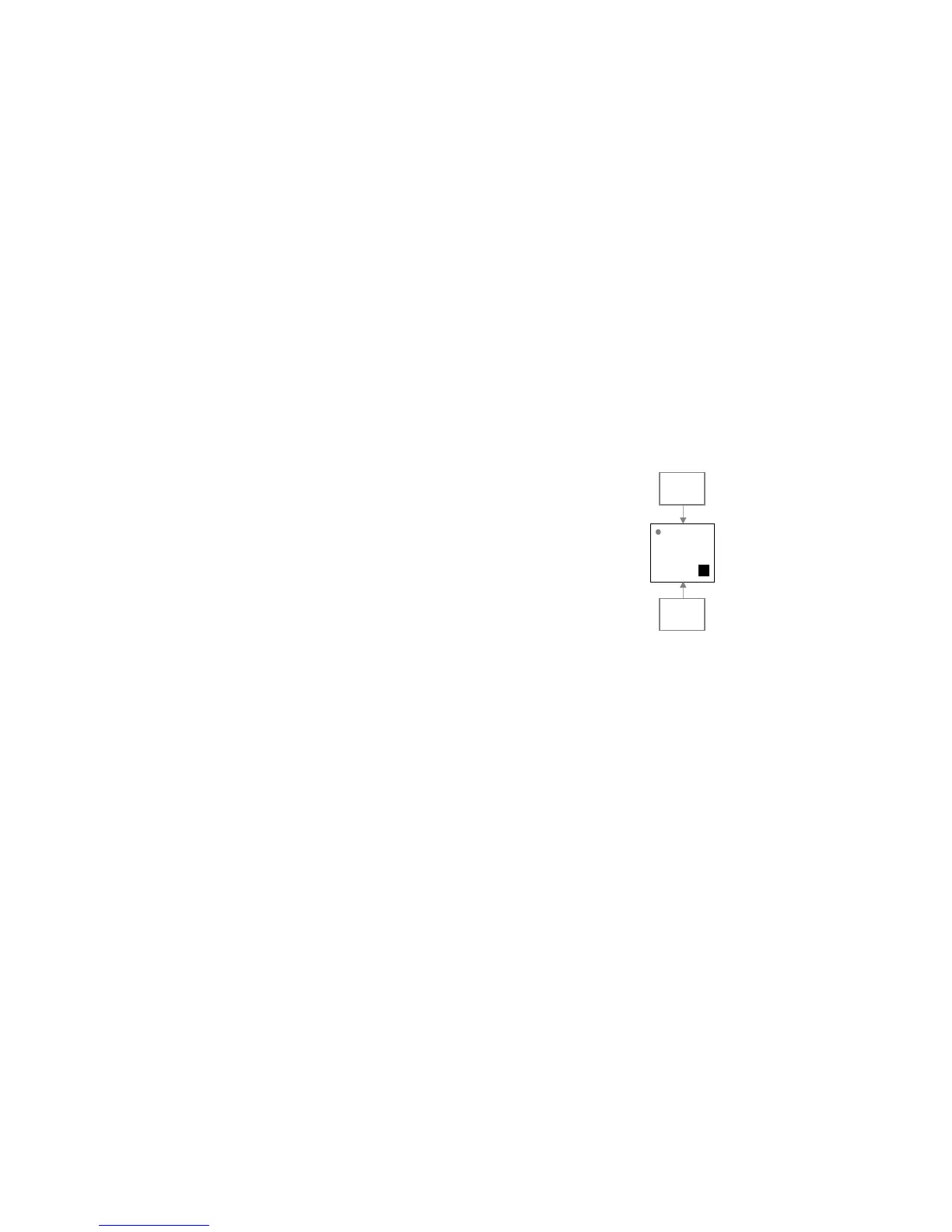
3. Connection of bus cables to NT-1 backing plate
• There are two terminal blocks on the backing plate of the
NT-1. One 2-wire bus cable must be dedicated to one of
brivis