the two terminal blocks and not shared across the two
blocks
• Draw both wires from the wall cavity and feed them through
the large slot in the backing plate
• Connect one of the 2-wire bus cables to the first terminal
block and the other 2-wire bus cable to the second terminal
block
4. Jumper Change for Unit Identification
• All NT-1 sensors are factory pre-set with unit identification
number “n02”. For multi-sensor systems additional NT-1
sensors must be assigned a unique unit identification
number. This is done by changing the jumper location from
“I/E” to: Refer to section 6.1.1 p.12
5. Mounting the backing plate
• Position the backing plate on the wall and mark the two
mounting positions on the wall
• Insert wall plugs (field supplied) in the marked positions to
suit the Ø3.5mm (6 gauge) screws supplied with the NT-1
• Secure backing plate to the wall, push back excess 2-wire
bus cable into the wall cavity and seal the hole to prevent
drafts
• Re-assemble the NT-1 - take care not to bend the
connector pins when re-assembling
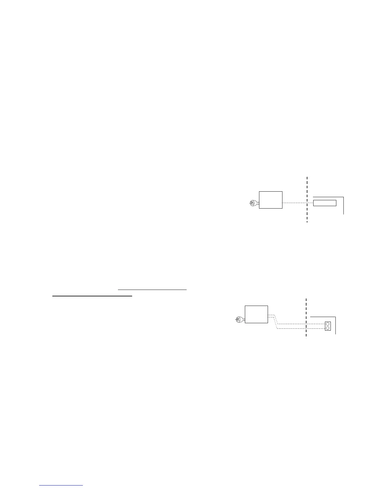
5.5 Brivis 516 Zone Module Installation
If a Brivis 516 low voltage Zone Module is required (see Table
2, p.6), install a 240VAC fixed switched GPO, installed
adjacent to the switched GPO for the heater.
Connect the 6 pin plug (loom) from the Zone Module to the
terminal marked "Ext Zone Module" on the heater control
board (see Diagram 4).
For detailed instructions please refer to the Brivis 516 Module
Installer’s Manual.
5.6 Brivis N-PM1 Power Module Installation
A Power Module is required when three or more NC-6
Networkers are part of the system (see Table 2, p.6).
The N-PM1 Power Module requires a 240VAC fixed switched
GPO, installed adjacent to the switched GPO for the heater.
Connect the 2-wire bus exiting the Power Module to the TW1
and TW2 terminals on the heater control board.
Diagram 5.
Diagram 4.
516 Module, Brivis Part No: B023178
240V,
50Hz
Plug
Loom