6.1.1 Setting NT-1 Sensor Identification
When the system contains more than one NT-1 device the
sensor identification parameter setting for additional sensors
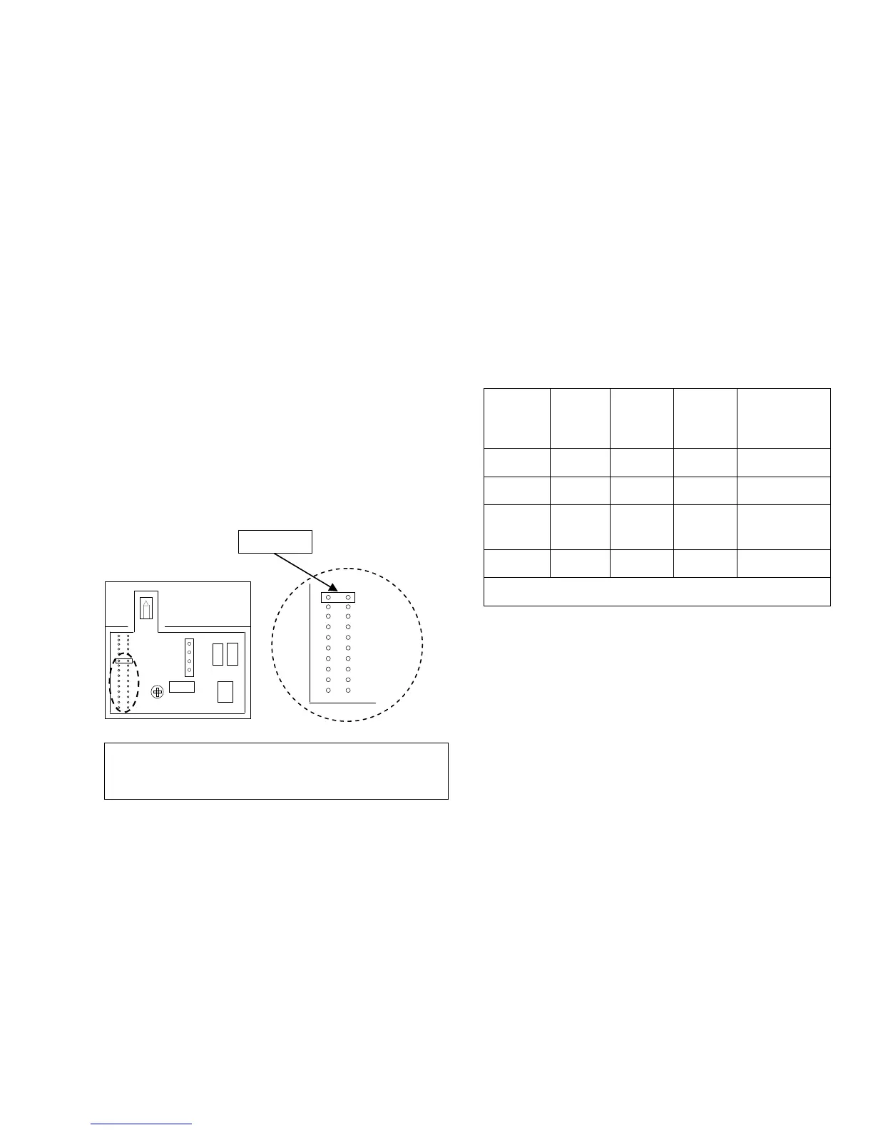
must be changed using the Jumper inside the NT-1.
JUMPER
For NT-1 sensors other than the NT-1 for Zone B, change the
default position of the Jumper pin from position “I/E” to
position:
“S3” for Zone C
“S4” for Zone D
Jumper pin positions “S5” to “S9” are reserved for future
development.
6.2 ZonePlus with Multiple NC-6 and NT-1
Sensors
Table 4: 4-Zone System Configuration with 2xNC-6 and 2x
NT-1 (example)
Zone ID
Sensor
Type
Sensor
ID
Factory
Setting
Sensor
ID
System
Setting
To modify
Sensor ID
System
Setting
Zone A NC-6 “n01” “n01” n/a
Zone B NT-1 “n02” “n02” n/a
Zone C NC-6 “n01” “n03”
Installer
Parameter
“ID00:3”
Zone D NT-1 “n02” “n04” Jumper “S4”
Always set and record all parameters in the Appendix.
Important Notes:
• NT-1 Sensors should be wired, configured and fully
installed
• Only the NC-6 Controller backing plates should be wired
and installed
Power up the system in the following sequence:
• 516 Network Module (if applicable)
• N-PM1 Power Module (if applicable)
• Heater
• Cooling System (if applicable)
S2
S3
S4
S5
S6
S7
S8
S9
AMBIENT
Diagram 7.
Note: NT-1 Temperature Sensors contain a green LED in the
top left hand corner. Whenever the NT-1 is being access by
an NC-6, the LED flashes once every second.