4 of 12 Fixed Rack Mount Kit Installation Procedure
53-1001274-02
Contents
This document provides instructions to install a 1U, 1.5U, or 2U switch (or SAN Router) in a 19-in. (48.3 cm) EIA
cabinet using the Fixed Rack Mount Kit. The document is organized as follows.
•Introduction . . . . . . . . . . . . . . . . . . . . . . . . . . . . . . . . . . . . . . . . . . . . . . . . . . . . 4
•Installation requirements . . . . . . . . . . . . . . . . . . . . . . . . . . . . . . . . . . . . . . . . . 5
•Tool requirements and parts list. . . . . . . . . . . . . . . . . . . . . . . . . . . . . . . . . . . . 5
•Installation procedure . . . . . . . . . . . . . . . . . . . . . . . . . . . . . . . . . . . . . . . . . . . . 7
Introduction
The supported switches are listed in Table 1. The switch can be installed so that the port side is either flush with the
front rails or recessed from the front rails. A recessed position allows a more gradual bend in the fiber optic cables
connected to the switch.
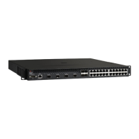
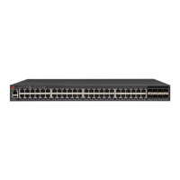
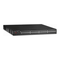
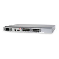
TABLE 1 Supported switches
Switch Height Switch Model
1U Brocade 200E
Brocade 300
Brocade 4100
Brocade 5000
Brocade 5100
Brocade 7500 series
Brocade 7600
Brocade 7800
Brocade 8000
2U Brocade 4900
Brocade 5300
Brocade AP7420
Brocade Encryption Switch
 Loading...