6 of 12 Fixed Rack Mount Kit Installation Procedure
53-1001274-02
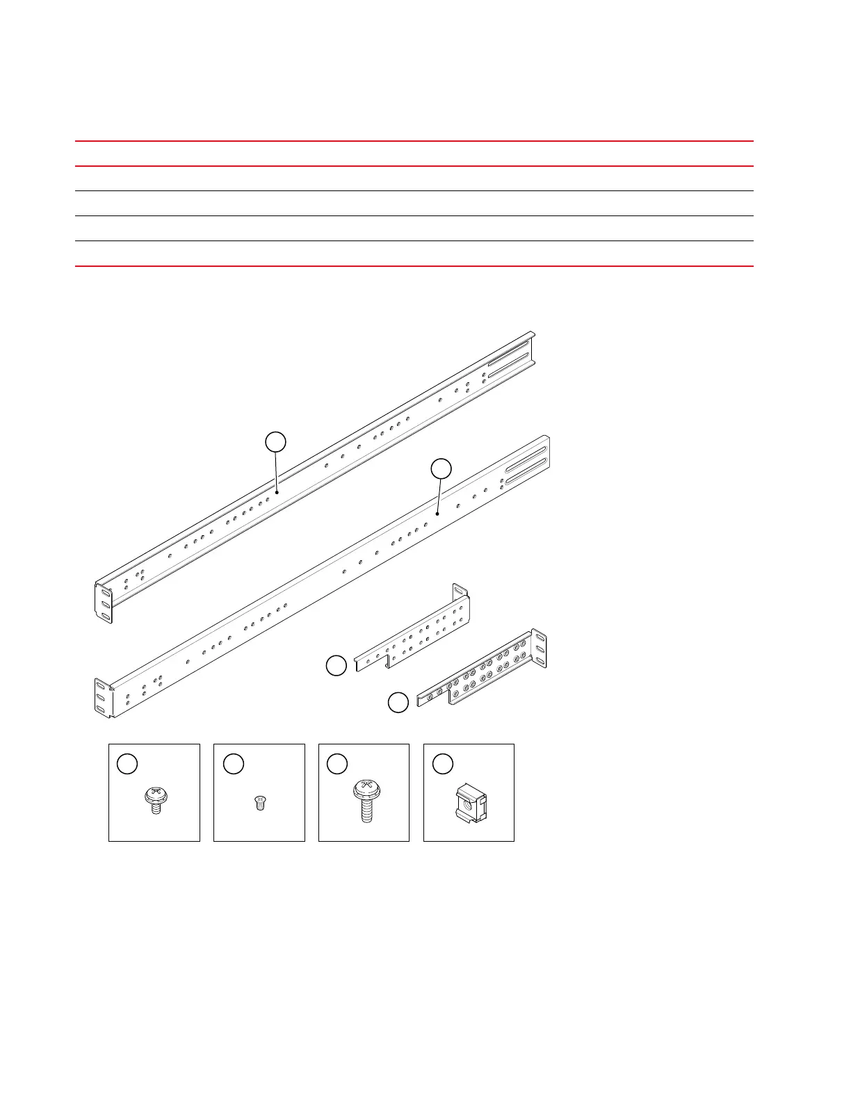
FIGURE 1 Items in Fixed Rack Mount Kit
5 Screw, 8-32 x 5/16 in., panhead Phillips (torque to 15 in.-lbs, 17 cm-kgs) 12
6 Screw, 6-32 x 1/4 in., flathead Phillips (torque to 9 in.-lbs, 10 cm-kgs) 8
7 Screw, 10-32 x 5/8 in., panhead Phillips (torque to 25 in.-lbs, 29 cm-kgs) 8
8Retainer nut, 10-32 8
1 Bracket, front right 5 Screw, 8-32 x 5/16 in., panhead Phillips
2 Bracket, front left 6 Screw, 6-32 x 1/4 in., flathead Phillips
3 Bracket, rear left 7 Screw, 10-32 x 5/8 in., panhead Phillips
4 Bracket, rear right 8 Retainer nut, 10-32
TABLE 2 Parts list
Item Description Quantity
scale: 3/16" = 1"
LEFT
RI
G
HT
#2-
0
00
2402-0
2
RE
V
.
B
FOX
C
ONN
01
/03
/
20
0
5
1
2
5
6
7
8
(8x)(8x)(12x) (8x)
(10-32)(10-32 x 5/8 in.)(6-32 x 1/4 in.)(8-32 x 5/16 in.)
3
4
 Loading...