8 of 12 Fixed Rack Mount Kit Installation Procedure
53-1001274-02
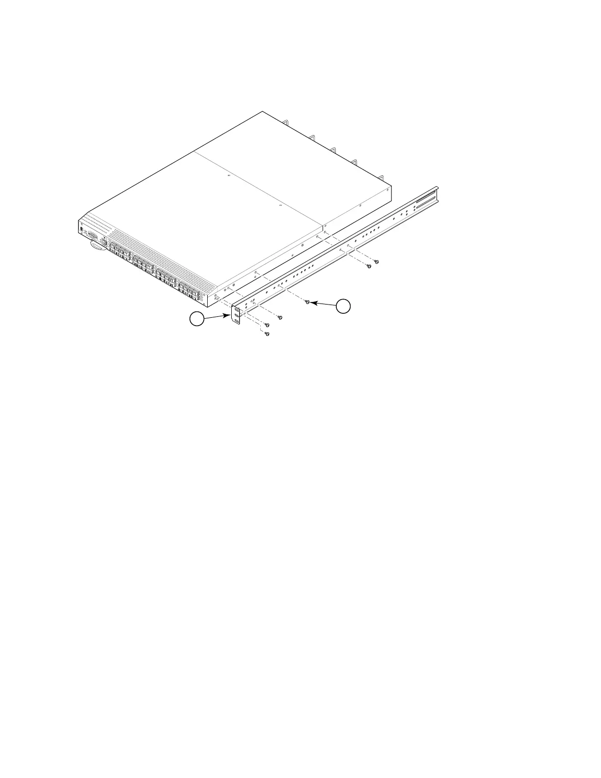
FIGURE 2 Position the front bracket
Installing the switch in the cabinet
Complete the following steps to install the switch in the cabinet.
1. Position the switch in the cabinet (Figure 3), providing temporary support under the switch until the rail kit is
secured to the cabinet.
2. Attach the right front bracket (Item 1) to the right front rack rail using two 10-32 x 5/8 in. screws (Item 7) and
two retainer nuts (Item 8).
3. Repeat step 2 to attach the left front bracket (Item 2) to the left front rack rail.
4. Tighten all 10-32 x 5/8 in. screws (Item 7) to a torque of 25 in.-lbs (29 cm-kgs
1 Bracket, front right
5 Screw, 8-32 x 5/16 in., panhead Phillips
scale: 1/8" = 1"
!
I
OI
O
I
S
i
l
k
W
orm 4
1
0
0
L
N
K
S
P
D
RIGHT
#
2
-0
0
0
2
4
0
2
-
0
2R
E
V.
B
F
O
XC
O
N
N
0
1
/
0
3
/
20
0
5
1
5
 Loading...