Fixed Rack Mount Kit Installation Procedure 9 of 12
53-1001274-02
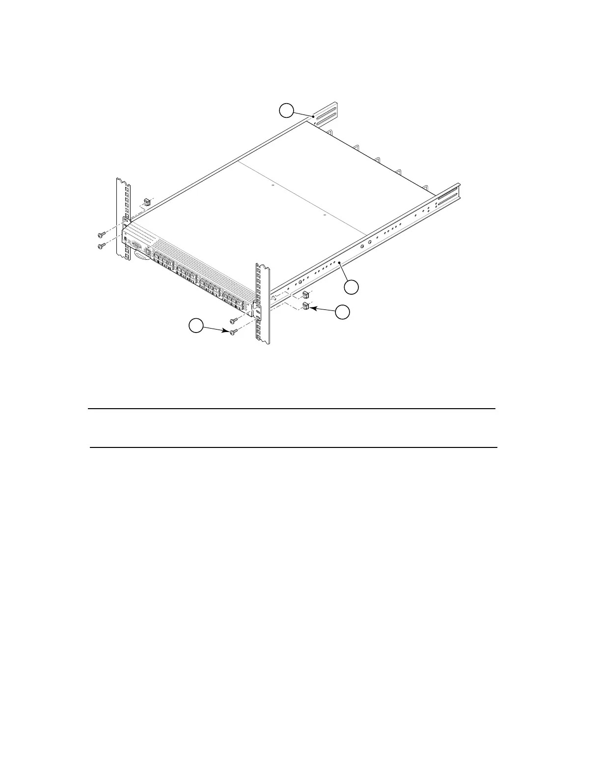
NOTE
The figure above is shown with a recessed mounting configuration on the left and a flush mounting
configuration on the right. You can select either mounting option.
FIGURE 3 Position the switch in the cabinet
Attaching rear brackets to front brackets
Complete the following steps to attach the rear brackets to the front brackets.
1. Position the right rear bracket (Item 4) inside the right front bracket (Item 1) (Figure 4).
2. Attach the brackets using four 6-32 x 1/4 in. screws (Item 6).
3. Adjust the brackets to cabinet depth and tighten the Item 6 screws to a torque of 9 in.-lbs (10 cm-kgs).
1 Bracket, front right 7 Screw, 10-32 x 5/8 in., panhead Phillips
2Bracket, front left 8Retainer nut, 10-32
scale: 1/8" = 1"
LEFT
!
I
O
I
O
I
S
i
l
k
W
o
r
m
4
1
0
0
L
N
K
S
P
D
RIG
H
T
#
2
-0
0
0
2
4
0
2
-
0
2
R
EV
.
B
F
O
X
C
O
N
N01
/
0
3
/
2
0
0
5
2
1
7
8
 Loading...