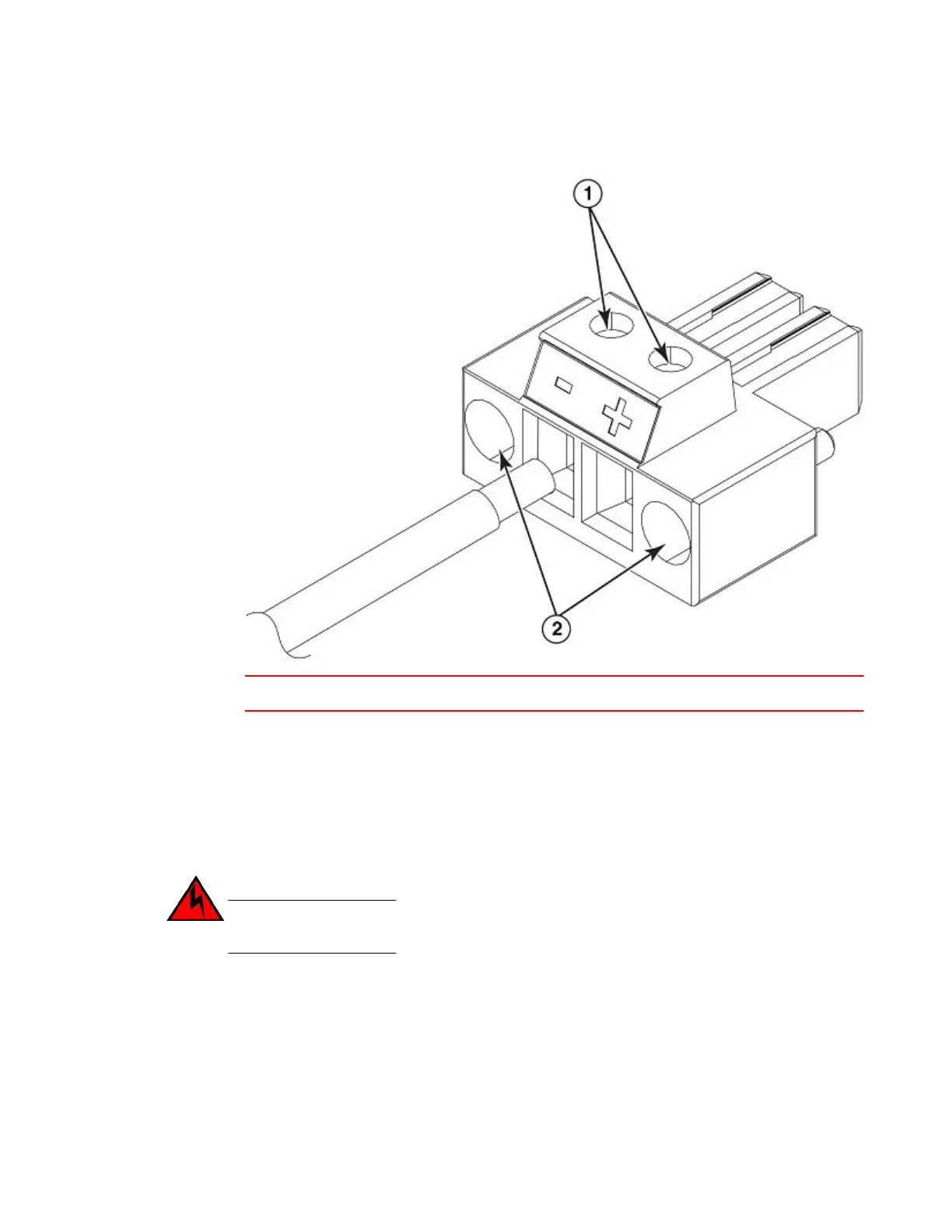
FIGURE 53 The DC wiring assembly
1 Wire tightening screws 2 Assembly screws
5. Pull the power supply outward once the screws have been unscrewed. This will disconnect the
power supply from the backplane. Pull it completely free of the chassis.
6. Place the power supply in an anti-static bag for storage.
7. Insert a new supply, or place and screw in a cover plate over the empty power supply. Refer to
Installing a DC power supply on page 86 for details.
Installing a DC power supply
DANGER
Before beginning the installation, refer to the precautions in Installing a DC power supply.
Use the following procedures for DC power supplies in Brocade devices.
Follow the steps given below to install an DC power supply.
1. If necessary, remove the power supply locking screws located in the upper left and the bottom right
of the device.
2. If the empty power supply bay has a cover plate, remove the two screws near the edges of the
cover plate to unlock the plate, then remove the plate.
3. Remove the DC power supply from its packaging (Installing a DC power supply).
Installing a DC power supply
86 Brocade NetIron CES 2000 Series and NetIron CER 2000 Series Hardware Installation Guide
53-1003823-01
 Loading...