2-5
OPERATION
INSTRUMENTS AND CONTROLS
The Broderson IC-35 instrument panel is equipped with a standard instrument package
showing electrical system amperage, fuel level, oil pressure, water temperature,
hydraulic oil temperature, and engine hours. Also included is a bubble level to level the
machine. (When unit is equipped with optional diesel engine, a glow plug light and glow
plug button are included.)
The IC-35 is equipped with a lighting package, including an on-off switch, two headlights
and two taillights. A horn button is located on the instrument panel.
The ignition switch is key operated and has ACC, IGN and OFF positions. The ignition
switch should always be turned off and the key removed when the vehicle is left
unattended
The hydrostatic transmission control switch is also located on the instrument panel. It
has FORWARD, NEUTRAL, and REVERSE positions. The speed of the transmission is
controlled by the engine speed, which is controlled with the accelerator pedal.
A pedal-activated brake is provided to hold the machine on slopes. Normal braking is
provided by the hydrostatic transmission when the accelerator pedal is released. The
brake pedal actuates disc brakes attached to each torque hub. The parking brake is
applied by a lever on the dash.
The steering wheel is directly mounted to the steering control unit of the all-hydraulic
power steering system. The system will provide limited steering if the engine stops
running.
The Rated Capacity Limiter display and input panel are mounted on the dashboard.
Instructions are in the RCL Operation Manual and additional information is in the
Operating the Crane section, the Crane Capacity section and Maintenance Section of
this manual.
CONTROL FUNCTIONS
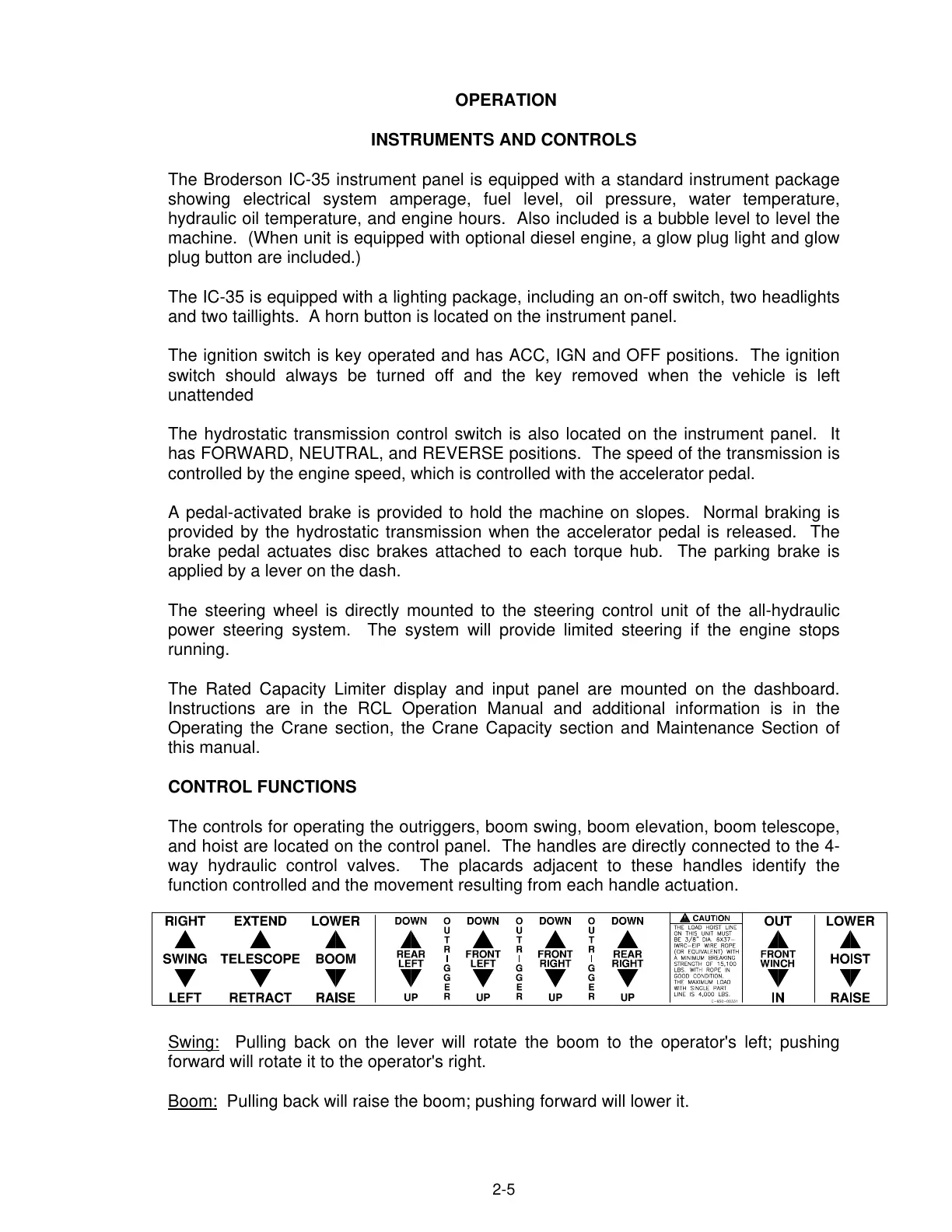
The controls for operating the outriggers, boom swing, boom elevation, boom telescope,
and hoist are located on the control panel. The handles are directly connected to the 4-
way hydraulic control valves. The placards adjacent to these handles identify the
function controlled and the movement resulting from each handle actuation.
Swing:
Pulling back on the lever will rotate the boom to the operator's left; pushing
forward will rotate it to the operator's right.
Boom:
Pulling back will raise the boom; pushing forward will lower it.
Courtesy of Crane.Market