Do you have a question about the Brother MFC-7220 and is the answer not in the manual?
Details the names and functions of the machine's external and internal components.
Lists and compares the technical specifications for various Brother facsimile and MFC models.
Explains the scanning, printing mechanisms, sensors, and control electronics.
Provides procedures for transferring fax data from a machine needing repair to prevent data loss.
Details procedures for disassembling and reassembling machine components, including torque values.
Outlines adjustments required after replacing major parts like the main PCB, CIS, or laser unit.
Provides cleaning procedures for the machine, referencing the User's Guide for specific parts.
Describes functions available in the maintenance mode for checks, settings, and adjustments.
Details error messages, codes, and troubleshooting steps for various machine malfunctions.
Explains the location and coding information for machine and laser unit serial number labels.
Provides instructions for updating firmware stored in the flash ROM on the main PCB.
Details how to set customizing codes for various preferences based on shipping destination.
Describes the functions of firmware switches used for customization and environmental matching.
Provides diagrams illustrating the connections between the machine's PCBs.
Presents the circuit diagrams for the NCU PCB and power supply PCB.
Shows where to attach specific caution labels on the machine.
Provides essential safety instructions for operating and maintaining the machine.
Recommends suitable placement for the machine based on environment and accessibility.
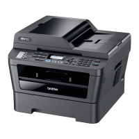
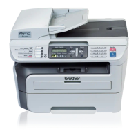
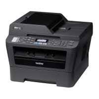
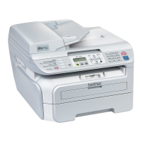
Provides an overview of the machine's external parts with front and rear views.
Details the layout and functions of the machine's control panel keys and display.
Describes the specific functions of One-Touch, Navigation, Mode, and other control panel keys.
Illustrates and lists the major internal components of the equipment.
Lists key technical specifications such as memory, ADF, power, dimensions, and weight.
Details paper types, sizes, weights, and other specifications for printing media.
Defines printable areas and provides toner cartridge weight information and print yield.
Compares detailed specifications across different Brother FAX and MFC models.
Provides a high-level block diagram of the machine's main components and interfaces.
Details the various mechanical parts and their functions within the printer and scanner mechanisms.
Illustrates the machine's hardware components and their interconnections, including PCBs.
Provides procedures for transferring fax data from a machine needing repair to prevent data loss.
Covers safety precautions, preparation steps, and how to access components for disassembly.
Outlines the disassembly sequence and covers removal of key components like trays and covers.
Details the process for removing various PCBs such as Hook PCB, NCU PCB, and Main PCB.
Details the disassembly of mechanical units like pickup rollers, fixing units, and motors.
Identifies specific points requiring lubrication during reassembly procedures.
Details adjustments needed after replacing main PCB, CIS, or laser unit.
Steps for loading firmware, initializing EEPROM, setting serial number, and adjusting scanner.
Procedure for acquiring white level data and setting CIS scanner area after CIS replacement.
Procedure for inputting the adjusted value of the laser scanner after replacement.
Provides cleaning procedures for the machine, referencing the User's Guide for specific parts.
Directs users to the User's Guide for cleaning procedures related to the drum unit and toner cartridge.
Describes the maintenance mode functions for checks, settings, and adjustments.
Explains how to enter the maintenance mode and allows limited user access to specific functions.
Provides a comprehensive list of available maintenance mode functions with their codes and references.
Details specific maintenance mode functions like EEPROM initialization, tests, and data outputs.
Covers error messages, codes, and troubleshooting procedures for equipment and communication issues.
Lists equipment errors with causes and actions, and provides detailed error codes for machine errors.
Addresses paper feeding problems and incorrect software settings that affect printing.
Provides steps for troubleshooting general malfunctions and specific image quality defects.
Offers guidance for network connectivity problems and fax function troubleshooting.
Explains the location and coding information for machine and laser unit serial number labels.
Provides instructions for updating firmware and setting machine ID codes via PC.
Details how to set customizing codes for various preferences based on shipping destination.
Describes firmware switch functions for dial, modem, function, and other settings.
Provides diagrams illustrating the connections between the machine's PCBs.
Presents the circuit diagrams for the NCU PCB and power supply PCB.
Shows where to attach specific caution labels on the machine.
| Print technology | Laser |
|---|---|
| Maximum resolution | 1200 x 600 DPI |
| Print speed (black, normal quality, A4/US Letter) | 20 ppm |
| PC free copying | Yes |
| Copy speed (black, normal quality, A4) | 20 cpm |
| Faxing | Mono faxing |
| Modem speed | 14.4 Kbit/s |
| Total input capacity | 250 sheets |
| Total output capacity | 100 sheets |
| Auto document feeder (ADF) input capacity | 20 sheets |
| Display | LCD |
| Market positioning | Home & office |
| Internal memory | 16 MB |
| Dimensions (WxDxH) | 452.12 x 492.76 x 429.26 mm |
| Power requirements | AC 120V 50/60Hz |
| All-in-one functions | Copy, Fax, Scan |
| Color all-in-one functions | |
| Compatible operating systems | Windows & Mac OS |
| Bundled software | Scansoft PaperPort SE with OCR for Windows and Presto PageManager for Mac |
| Sustainability certificates | ENERGY STAR |
| Power consumption (off) | 10 W |
| Power consumption (standby) | 75 W |
| Power consumption (average operating) | 1032 W |
| Operating temperature (T-T) | 50 - 91 °C |
| Non-operating relative humidity (non-condensing) | 20 - 80 % |
| Digital sender | No |
| Maximum duty cycle | 10000 pages per month |
| Weight | 10795 g |
|---|