Confidential
3-17
3.3 CONTROL ELECTRONICS
3.3.1 Components
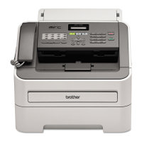
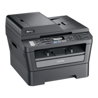
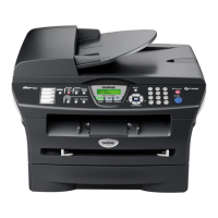
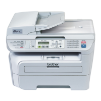
The following illustration shows the hardware components for this machine. The corresponding
connection diagram appears in Appendix 5.
Main PCB
12-pin
ROM MODEM
SDRAM
NCU PCB
2-pin
Speaker
Control panel
6-pin
THM
4-pin
17-pin
19-pin
7-pin
CIS unit
2-pin
Cover sensor
Handset
Line
External telephone
LAN
PC
*
1
High voltage PS PCB Toner sensor
EEPROM
2-pin
Scanning motor F
Hook
2-pin
2-pin
2-pin
2-pin
Backup battery
LAN I/F
USB
Power supply PCB
AC line
Main
ASIC
4-pin (with Handset model)
12-pin (with/out Handset model)
4-pin
Main motor
Fan (Large)
New toner sensor
20-pin
2-pin 2-pin 2-pin
CDCC
6-pin
15-pin
Laser diode
Scanner motor
2-pin
STHM
PC
Parallel PCB
Heater
Toner LED
Fan 40
*
1
NCU1
NCU2
: MFC7225N only
11-pin (with Handset model)
< Machine Components >
 Loading...

