CONTENTS
CHAPTER I SPECIFICATIONS
1.1 Mechanical Specifications .........................................................................................................I-1
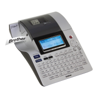
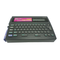
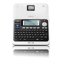
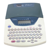
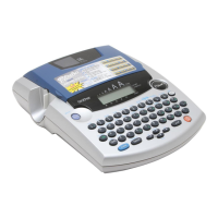
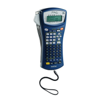
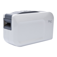
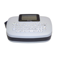
1.1.1 External Appearance ...........................................................................................................I-1
1.1.2 Keyboard .............................................................................................................................I-1
1.1.3 Display.................................................................................................................................I-1
1.1.4 Printing Mechanism.............................................................................................................I-2
1.1.5 Tape Cutter ..........................................................................................................................I-2
1.2 Electronics Specifications..........................................................................................................I-7
1.2.1 Character Generator.............................................................................................................I-7
1.2.2 Power Supply.......................................................................................................................I-7
1.3 Key Commands for Special Functions ......................................................................................I-7
1.3.1 Initializing............................................................................................................................I-7
CHAPTER II THEORY OF OPERATION
2.1 Main Mechanisms.................................................................................................................... II-1
2.1.1 Roller Holder ASSY Setting & Retracting Mechanism .................................................... II-1
2.1.2 Tape & Ribbon Feed Mechanism...................................................................................... II-2
2.1.3 Automatic Tape Cutter Mechanism................................................................................... II-4
2.1.4 Roller Holder ASSY & Cassette Cover Interlocking Mechanism .................................... II-5
2.2 Outline of Control Electronics................................................................................................. II-6
2.2.1 Configuration..................................................................................................................... II-6
2.2.2 Main PCB .......................................................................................................................... II-8
[ 1 ] Block Diagram................................................................................................................. II-8
[ 2 ] Cassette Sensor................................................................................................................ II-9
CHAPTER IIIDISASSEMBLY & REASSEMBLY
3.1 Disassembly/Reassembly ....................................................................................................... III-3
3.1.1 Disassembly Procedure .................................................................................................... III-3
[ 1 ] Removing the Tape Cassette and the Cassette Cover ASSY ......................................... III-3
[ 2 ] Removing the Battery Lid and the Dry Cells ................................................................. III-4
[ 3 ] Removing the Bottom Cover, the Blind Cover and the Battery Terminals.................... III-5
[ 4 ] Removing the Chassis ASSY ......................................................................................... III-7
[ 5 ] Disassembling the Chassis ASSY .................................................................................. III-9
[ 6 ] Removing the Power PCB ASSY ................................................................................ III-16
[ 7 ] Removing the Cassette PCB ASSY ............................................................................. III-17
[ 8 ] Removing the PCB Holder, the Main PCB ASSY and the LCD Module ASSY ........ III-18
[ 9 ] Removing the Frame Cover.......................................................................................... III-21
[ 10 ] Removing the Rubber 68 Key ...................................................................................... III-22
[ 11 ] Removing the LCD Panel............................................................................................. III-23
[ 12 ] Removing the Anti Static Brush................................................................................... III-24
3.1.2 Reassembly Procedure.................................................................................................... III-25
[ 1 ] Installing the Anti Static Brush .................................................................................... III-25
[ 2 ] Installing the LCD Panel .............................................................................................. III-26
[ 3 ] Installing the Rubber 68 Key........................................................................................ III-27
[ 4 ] Installing the Frame Cover ........................................................................................... III-28

 Loading...