III - 34
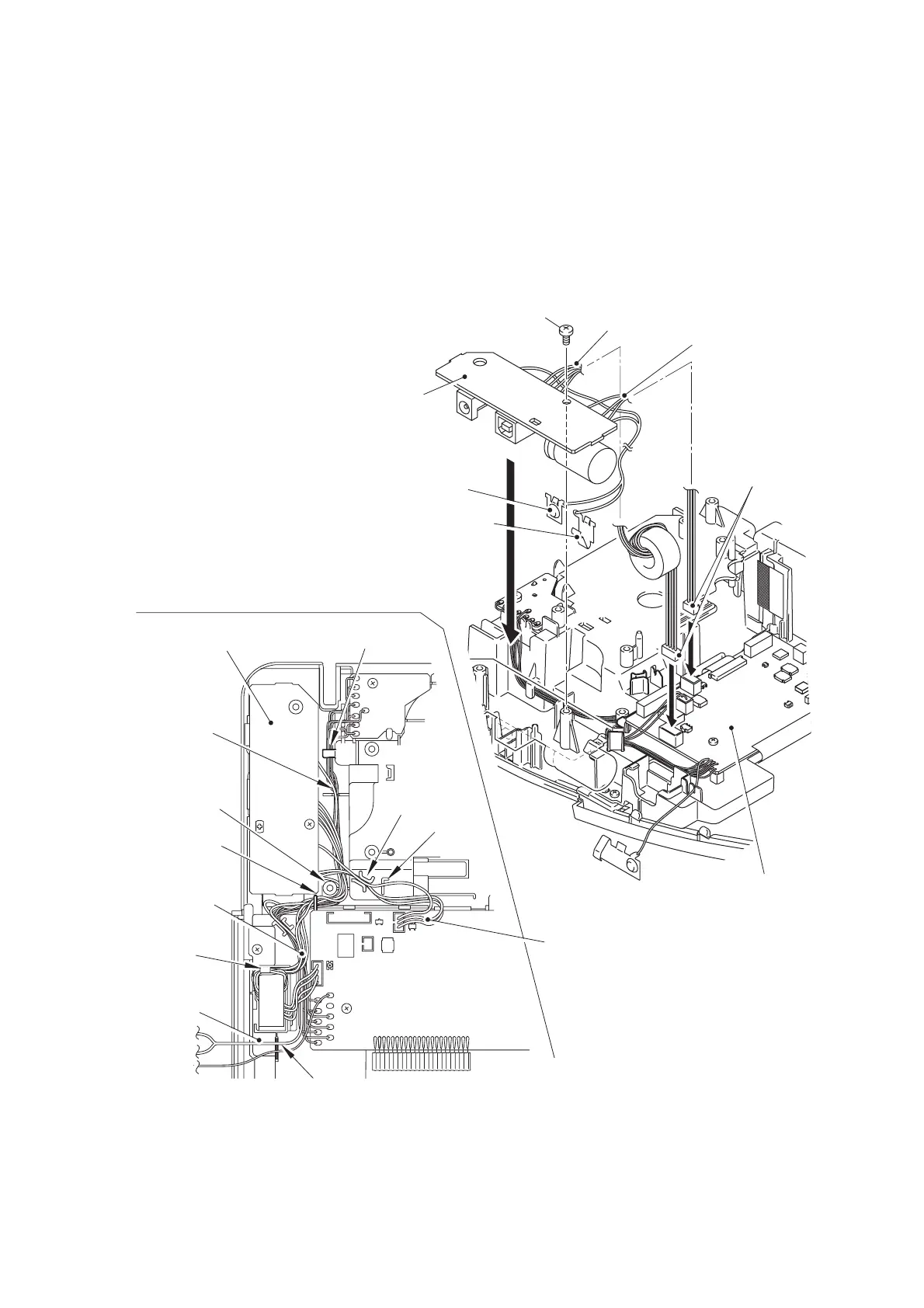
[ 7 ] Installing the Power PCB ASSY
CAUTION: When handling the PCBs, put on the grounding wrist band. Failure to do
so might break LSIs and other electronic devices.
(1) Set the power PCB ASSY to the upper cover with the screw.
(2) Connect the two connectors of the power PCB ASSY to the main PCB ASSY.
NOTE: When wiring, pass the lead wires through the guides and the slits as shown the
below figure.
Figure 3.1-38 Installing the Power PCB ASSY
Power PCB ASSY
Power PCB ASSY
Positive battery terminal
Negative battery terminal
Positive, Negative
battery terminal leads
Power PCB ASSY
leads "A"
Power PCB ASSY
leads "B"
Power PCB ASSY
leads "B"
Power PCB ASSY
connectors
Power PCB ASSY
leads "A"
Main PCB ASSY
Main PCB ASSY
Guide
Guide
Guide
Guide
Hook
Slit
Slit
Slit
Screw

 Loading...