10
BOAT RIGGING
REMOTE CONTROLS
Control Cable Routing
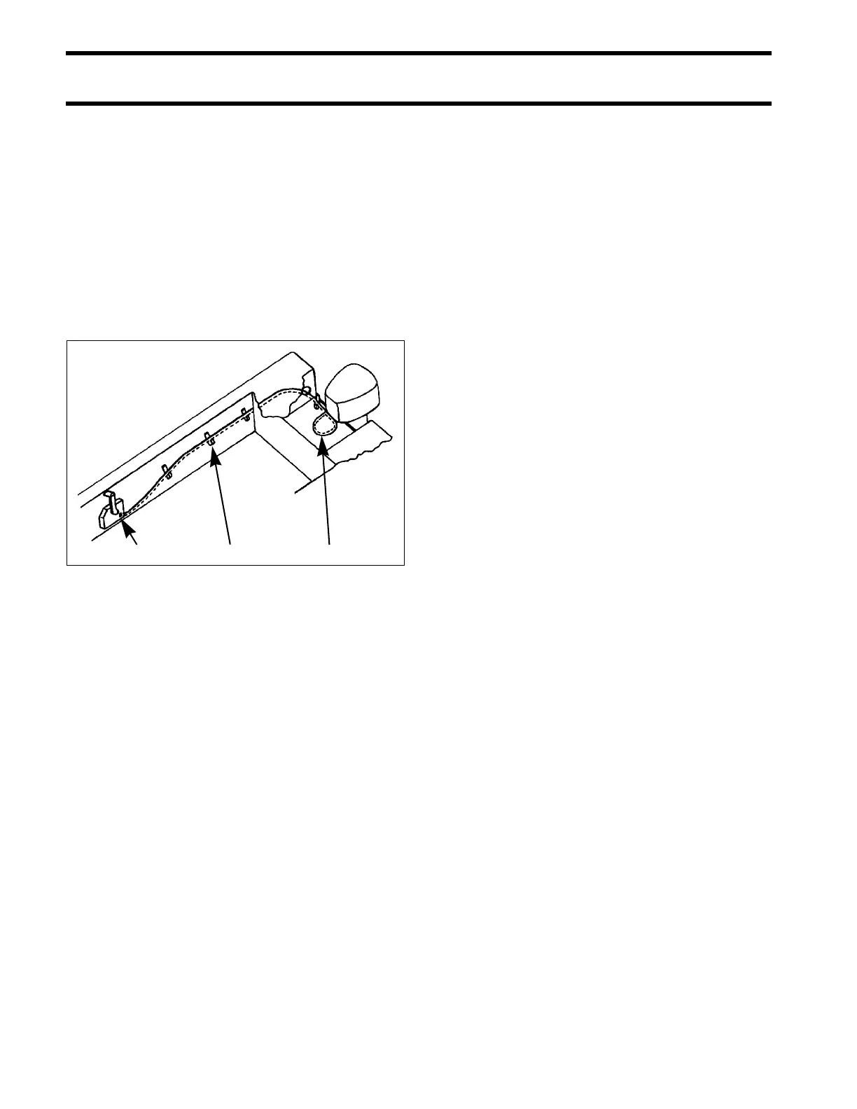
Control cables and harnesses should be routed
along a protected path to the rear of the boat and
secured to prevent movement or damage.
Harness connections should be moun ted in a dry
location, away from bilge and motor well areas.
Control cables should be long en ough t o allow a
12 in. (30 cm) cable loop at the fro nt of the out-
board when the cables are routed from the side of
the splash well.
Evinrude ICON Networks
All control infor mation is transferred between the
outboard and an Evinrude ICON system through a
single network cab le. For comple te installation
instructions, refer to the Evinrude ICON Remote
Control System Installation Guide, P/N 764952.
When installing an ICON network, remember:
• Control network must include two cable hubs
• DO NOT use the key switch to power accesso-
ries (switched B+)—use an ICON Accessory
Power Relay Kit
• The ICON Gateway provides a conne ction for
an I-Command Information Display network.
Refer to Evinrude ICON / I-Command Harness
Connections on p. 14 for a typical network instal-
lation diagram.
1. Surface side-mount remote control
2. Cable support
3. 12 in. (30 cm) cable loop at front of outboard
DR4277