33
OUTBOARD INSTALLATION
TRANSOM MEASURING AND DRILLING
2
TRANSOM MEASURING
AND DRILLING
Hull Centerline
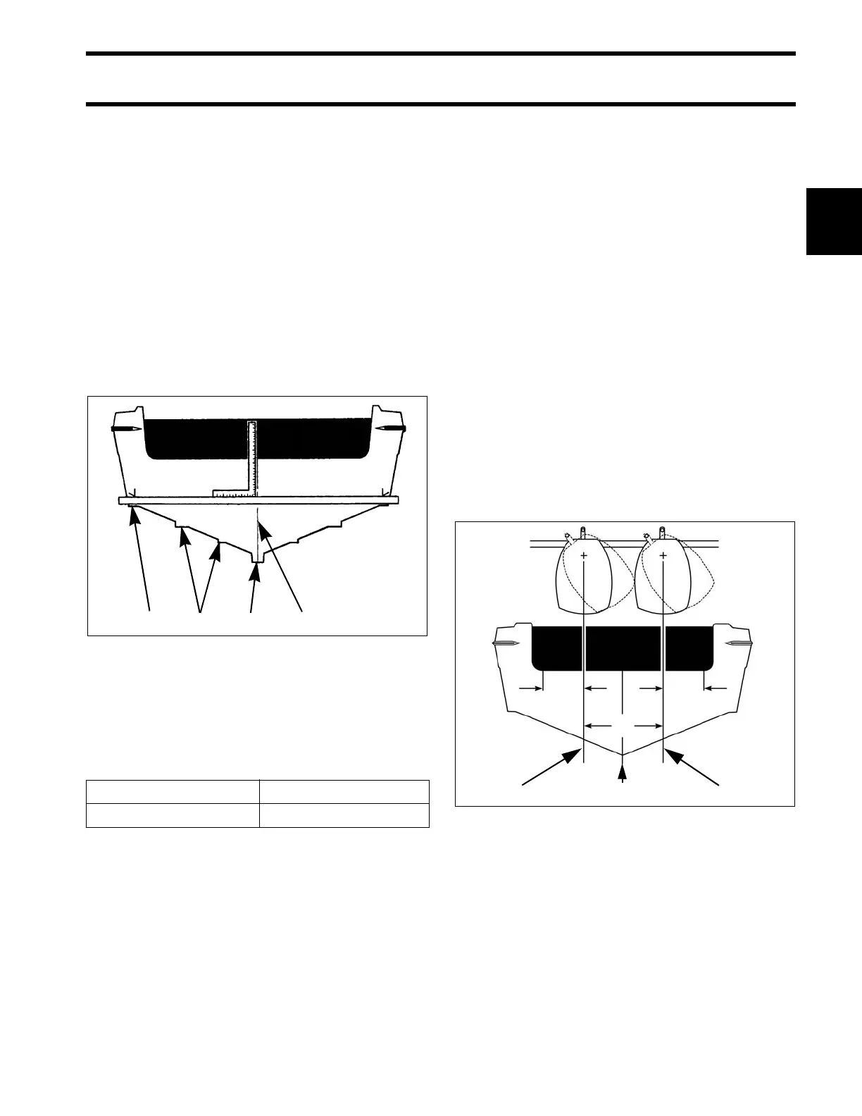
Use the chines of the boat as ref erence points to
locate the centerline of the boat transom.
Use a straightedge to draw a lin e connecting the
port and starboard chines.
Use a framing square to a ccurately place a verti-
cal line on the transom. The centerline of the hull
should be in line with t he keel, and perpendicular
to the midpoint of the line connecting the chines.
Dual-Outboard Centerlines
The following table lists standard ABYC centerline
spacing between outboards in dual installations:
Some app lications may re quire changes in this
dimension to a void strakes, to a djust for t ransom
height, or for perfo rmance reasons. Best perfor-
mance ca n be d etermined only thro ugh te sting.
Refer to boat manufacturer for recommendations.
If the standard spacing does not allow full steering
travel in a p articular installation, it ma y be n eces-
sary to increase the spacing.
IMPORTANT: Some s teering systems m ay
require additional spacing. Refer to steering sys-
tem manufacturer for recommendations.
The top edge of the transom should be more than
twice the wid th of the du al-outboard centerline
spacing dimension. Bracket inst allations may not
require this consideration.
Measure the tra nsom for dua l-outboard sp acing
after the centerline of the hull is established.
Divide th e sp acing dimension by two. Use the
resulting number t o sp ace the o utboard cen ter-
lines from the hull centerline.
EXAMPLE: A 26 in. (660 mm) dual-outboard
spacing would result in two out board centerlines,
each 13 in. (330 mm) from the hull centerline.
1. Chine
2. Strake
3. Keel
4. Hull centerline
DR5568
2 and 3 cylinder 22 in. (559 mm)
V4 and V6 26 in. (660 mm)
1. Port centerline
2. Hull centerline
3. Starboard centerline
DRC5527B