9
BOAT RIGGING
REMOTE CONTROLS
1
Control Installation
Plan the inst allation of re mote co ntrols carefully,
following all instructions provided with the control.
Select an appropriate location based on the boat
configuration.
IMPORTANT: The mounting location must be a
flat surface and must be strong enough to provide
rigid support. S trengthen moun ting surface a s
necessary.
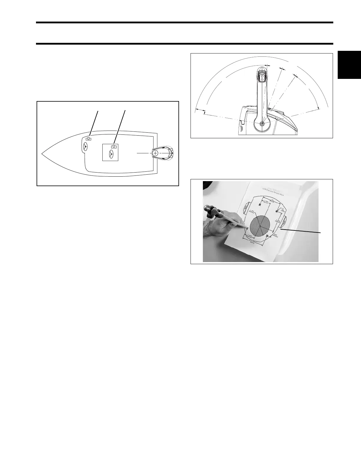
Place remote cont rol at proposed locatio n and
check clearan ce a round remote con trol leve r at
full throttle in FORWARD and then at full throttle in
REVERSE. There must be at least 2.5 in. (64 mm)
of clearance between the handle and any part of
the boat throughout the control lever travel.
Use an app ropriate drill template to cut mo unting
holes. T emplates are includ ed with the control
instructions.
Install control with hardware provided.
IMPORTANT: Make sure remote control assem-
bly is secure and does not move during operation.
1. Side console
2. Center console
005471
Typical control clearances 007920
1. Template 007922
85.5°
FWD
15.0°
15.0°
40.5°
NEUTRAL
REV
2.5 in (64 mm)