13
BOAT RIGGING
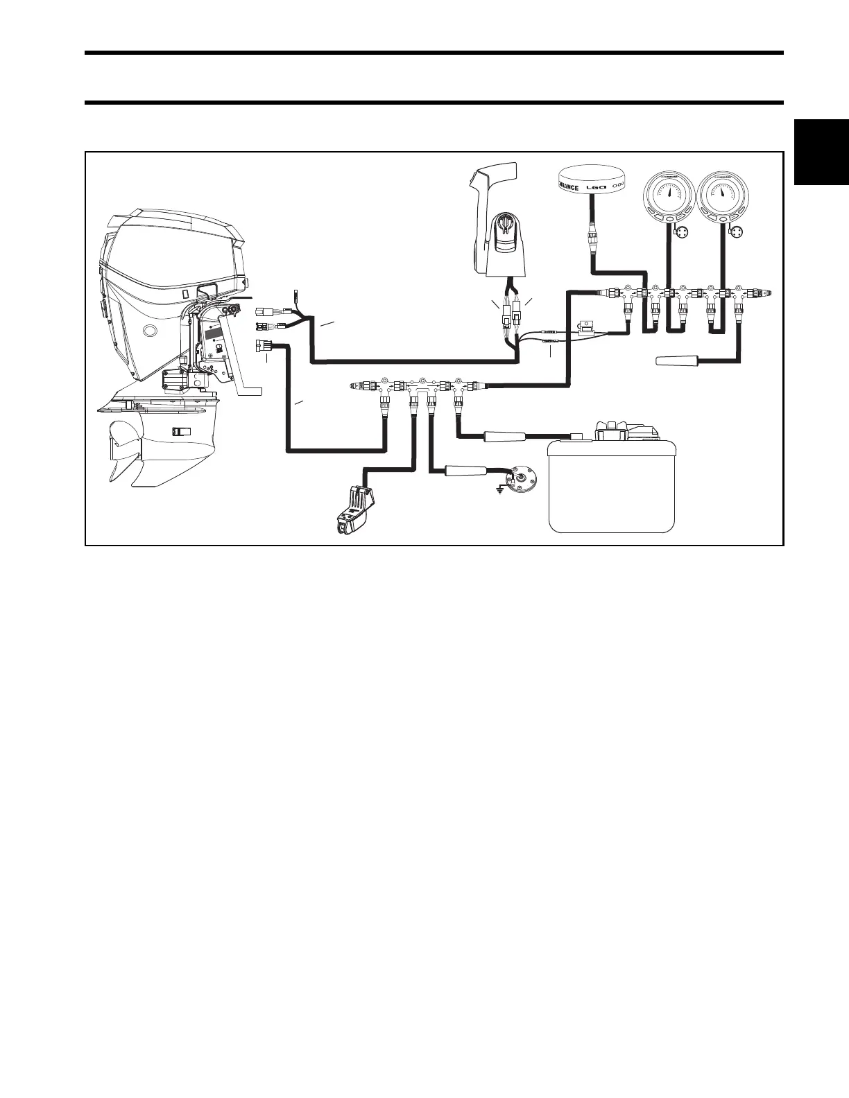
INFORMATION DISPLAY SYSTEMS
1
I-Command Harness Connections With Mechanical Remote Control
BUSSBUSS
BUSSBUSS
3A
DEVICEDEVICE
DEVICEDEVICE
DEVICEDEVICE
DEVICEDEVICE
DEVICEDEVICE
BUSSBUSS BUSSBUSS BUSSBUSS
EP- 85 Memory Module
DEVICE
DEVICE
DEVICE
DEVICE
BUSS BUSSBUSS
BUSSBUSS
MENU
DOWN
UP
EXIT
PAGES
ENTER
15
10
5
0
20
25
30
35
40
Water
MPH
15.2
MENU
DOWN
UP
EXIT
PAGES
ENTER
30
20
10
0
40
50
60
70
x 100
RPM
3550
1
3
4
2
5
6
Typical I-Command wiring with a binnacle-mount mechanical remote control 007990
1. I-Command Ignition and Trim Harness
2. I-Command Network Harness
3. 6-Pin Connector – Connect to a pre-wired remote control or to a dash-mounted key switch.
4. 3-Pin Connector – Connect to remote control trim switch or to a dash-mounted trim switch.
5. Purple, black wires – Connect to network power supply.
6. 4-Pin Amp Connector – Connect to outboard EMM.