71
OUTBOARD RIGGING
EVINRUDE E-TEC MODELS 15–30 HP
3
EVINRUDE E-TEC
MODELS 15–30 HP
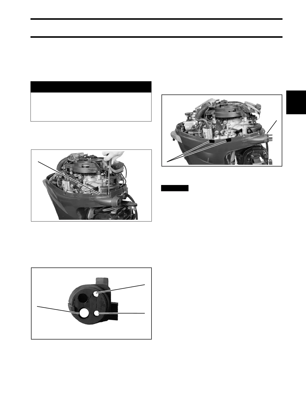
Cable, Hose, and Wire Routing
Refer to Control Cable Identification on p. 51.
Remove cable entry grommet cover and grommet.
Remove rubbe r membrane from grommet hole s
as needed.
Install cables and wiring h arness(es) throu gh
grommet as shown:
When g rommet is in p lace and all cables have
been installed, tighten a tie strap around the out-
side of the gromme t to form a watertight sea l
around the cables.
Place blank sealing decal on lip of lower mo tor
cover at each ha rness connector tie stra p to p re-
vent water intrusion.
After installation, make sure there
is enough clearance for all cables to avoid
binding or chafing through all engine steering
and tilting angles.
Control Cable Installation
Refer to Control Cable Identification on p. 51.
Make sure the remote control is in NEUTRAL, and
throttle is in the IDLE position.
Removal of lower m otor covers is NOT re quired.
Some image s show lower cove rs re moved for
clear illustration.
Place the shift cable on the shift lever pin.
Hold the shift linkage in NEUTRAL.
Push and p ull on the shift cable and observe the
cable slack. Hold the casing guide in the center of
the slack.
A CAUTION
To prevent accidental starting while servic-
ing, disconnect the battery cables at the
battery. Twist and remove all spark plug
leads.
1. Cable entry grommet cover 007120
1. Throttle cable
2. Shift cable
3. Electrical harness
007129
1. Tie strap
2. Blank sealing decal
007127