54
OUTBOARD RIGGING
EVINRUDE E-TEC 90° V MODELS 200–300 HP
Make sure that idle stop of the throttle lever is
against the crankcase.
Adjust the throttle cable trunnion to align with the
trunnion block. Place the ca ble trun nion in the
trunnion block.
IMPORTANT: Move control handle to FOR-
WARD and pull back slowly t o NEUT RAL. Make
sure the engine throttle lever is against the stop. If
not, remove slack by adjusting cable trunnion.
Install trunnion cover and screw. Tighten screw to
a torque of 60 to 80 in. lbs. (7 to 9 N·m).
Battery Cable Connections
Install battery cables on starter solenoid and main
ground stud.
SystemCheck Harness
Connections
Remove harness connector cover.
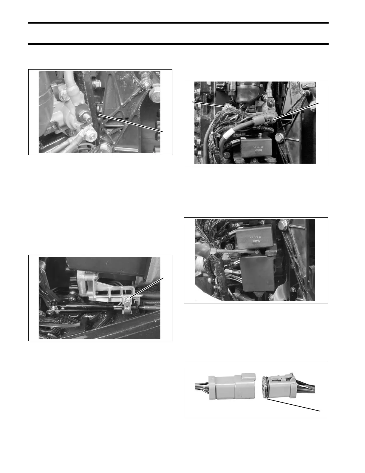
Before installing electrical connectors, check th at
the seal is in place. Clean of f any dirt from con-
nectors. Apply a light coat of Electrical Grease to
the seal only. DO NOT fill connectors with Electri-
cal Grease.
1. Throttle lever stop 003968
1. Trunnion cover and screw, throttle cable 005039
1. Positive (+) battery connection
2. Ground (–) connection
003975
003972
1. Seal 42079A