EasyManuals Logo

BST ekr 500 digital Unit Touch User Manual

BST ekr 500 digital Unit Touch
45 pages
To Next Page IconTo Next Page
To Previous Page IconTo Previous Page
Page #18 background imageLoading...
Page #18 background image
5
Electrical Connection
18/45 ekr 500 digital Unit Touch – Master-Slave Guiding with Sensor Positioner
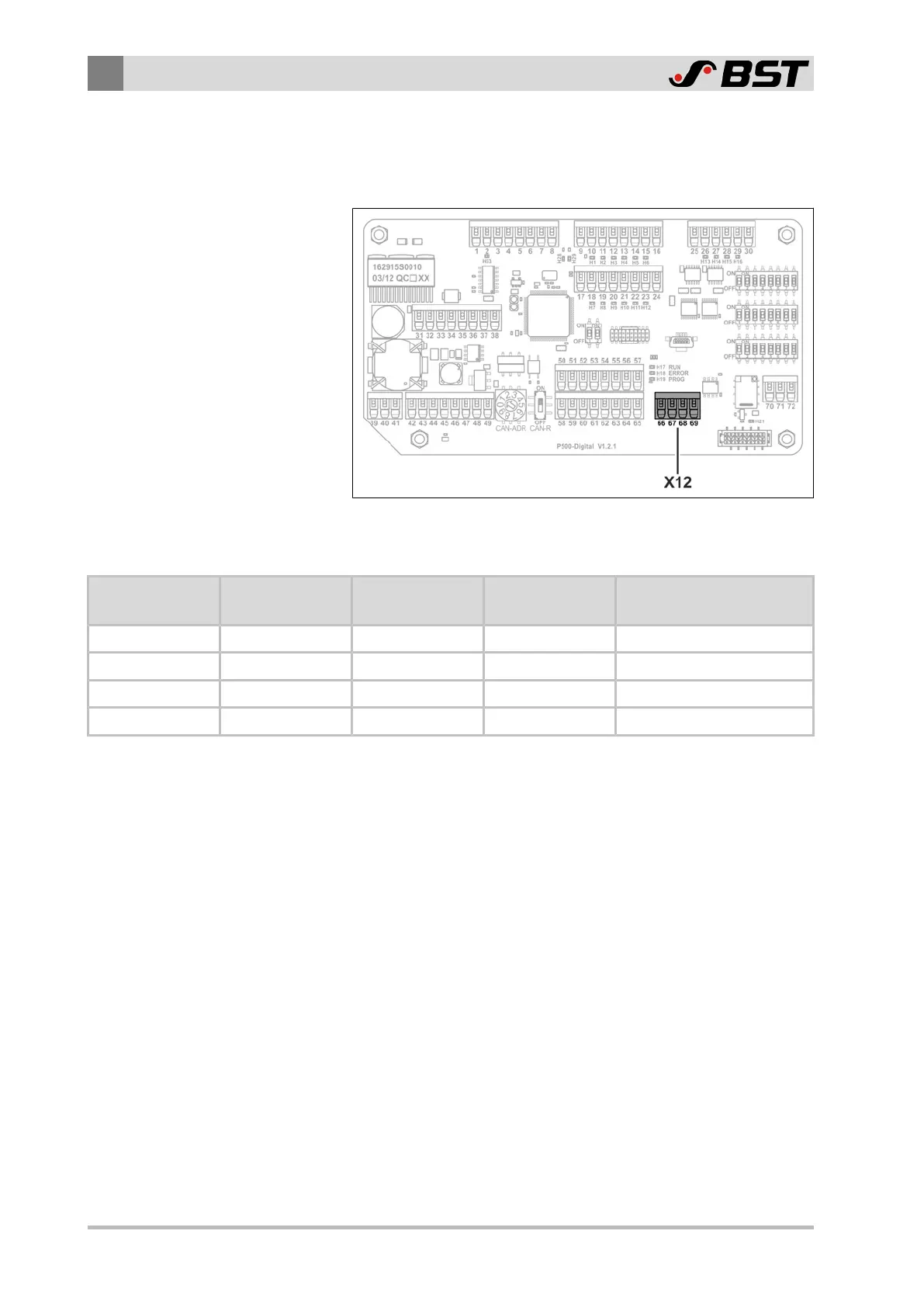
5.3.3 Terminal Assignment of Terminal Strip X12 (Connection Sensor 4)
The following figure shows the position of the terminal strip X12
on the processor board of the controller.
Fig.5: Processor board of the controller
Terminal Assignment
X12
Terminal
X104
Pin
Function Wire Colour Note
66 1 +24V brown Power supply Sensor4
67 2 CAN4-H white CAN4 high
68 3 GND blue Ground CAN4
69 4 CAN4-L black CAN4 low

Table of Contents

Other manuals for BST ekr 500 digital Unit Touch

Questions and Answers:

Question and Answer IconNeed help?

Do you have a question about the BST ekr 500 digital Unit Touch and is the answer not in the manual?

BST ekr 500 digital Unit Touch Specifications

General IconGeneral
BrandBST
Modelekr 500 digital Unit Touch
CategoryController
LanguageEnglish

Related product manuals