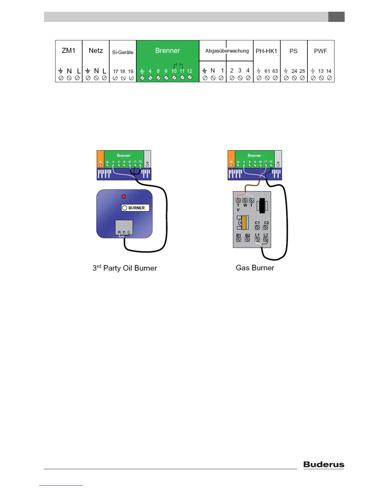
EasyManuals Logo

Buderus Logamatic 2107 Installation And Service Instructions

Buderus Logamatic 2107
72 pages
To Next Page IconTo Next Page
To Previous Page IconTo Previous Page
Page #63 background imageLoading...
Page #63 background image
Oil burners factory jumper between terminals 12 & 10,
brings 120V from 12 to 10. When contacts close
between terminals 10 & 11, 120V power is sent from
terminal 11 to Hot on the burner (terminal 4 is the
neutral).
Gas burners remove factory installed jumper between
terminals 10 & 12. The contacts between terminals 10 &
11 are now “dry” (no voltage present) and switching to
the burner is now low voltage between terminals 10 & 11
on the R2107 and TT (or RW) on the boiler aquastat.
Logamatic 2107 controls - We reserve the right to make any changes due to technical modifications. 63
20
Troubleshooting

Table of Contents

Other manuals for Buderus Logamatic 2107

Questions and Answers:

Question and Answer IconNeed help?

Do you have a question about the Buderus Logamatic 2107 and is the answer not in the manual?

Buderus Logamatic 2107 Specifications

General IconGeneral
CategoryControl Systems
TypeHeating Control Unit
Voltage230 V
Frequency50 Hz
Protection classIP20
Ambient temperature0°C
ApplicationHeating systems

Related product manuals