34
Installation and maintenance instructions Logano G334 X gas-fired boiler • Issue 09/2005
We reserve the right to make any changes due to technical modifications.
Placing the heating system in operation11
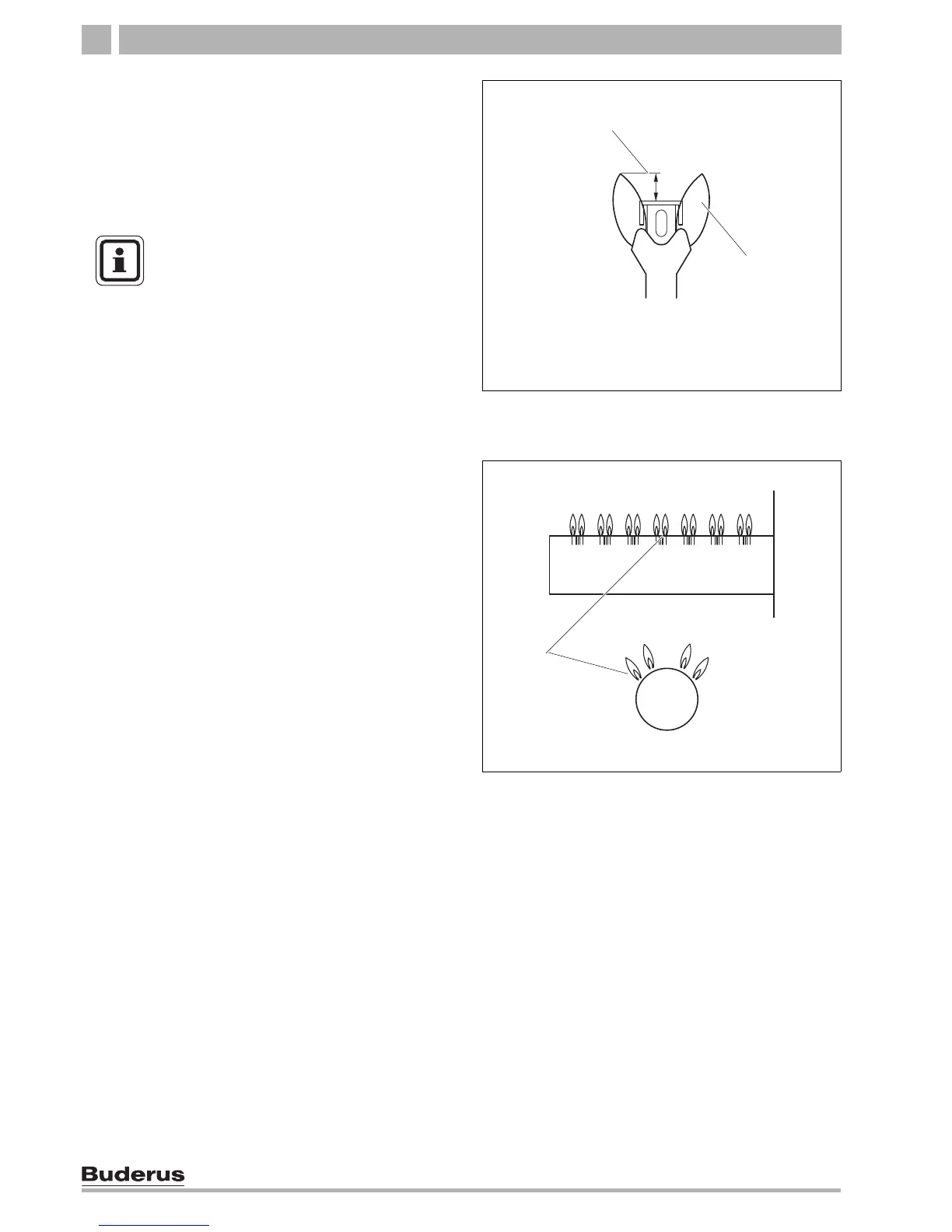
15. Observe pilot flame through the sight glass (Î Fig.
27, page 32) in the burner housing.
16. The flame must envelope the flame guard 1/2 to 1
1/2 inches. If this is the case continue with step 20.
17. If the pilot flame is too small or too large, the
pressure for the pilot must be adjusted with the
corresponding adjustment screw.
18. Remove safety screw for pilot pressure setting
(Î Fig. 28, page 33). Turn the inner adjustment
screw clockwise to reduce the pilot flame and
counterclockwise to enlarge the pilot flame.
19. After adjustment tighten the pilot gas pressure
adjustment safety screw
(Î Fig. 28, page 33) again.
20. Observe main burner flame through the sight glass
(Î Fig. 27, page 32) in the burner housing. The
flame must have a steady and fixed contour and
generally has a bluish color. If the main burner flame
meets the requirements, proceed with step 21. If the
main burner flame is too weak or is yellow or goes
out, turn the ON/OFF switch
(Î Fig. 28, page 33) on
the gas valve clockwise to OFF. Close the gas shut-
off valve and disconnect the heating system from the
power supply and contact the customer service
technician or the gas company.
Checking ignition safety switch
21. Test the safety switch by closing the gas shut-off
valve. The main burner flame
(Î Fig. 30) and the
pilot flame (Î Fig. 29) are extinguished. After six (6)
seconds at the most the main gas solenoid valve on
the gas valve must close with an audible noise.
22. After 90 seconds the automatic igniter must switch
to lock status and stop generating sparks.
23. Disconnect the heating system from the power
supply. Open main gas valve. Switch on unit power
supply. A normal operating cycle must follow.
24. If the gas valve operates correctly, proceed to step
25. If the gas valve does not operate correctly,
switch ON/OFF switch
(Î Fig. 31) on the gas valve
clockwise to the OFF position immediately. Close
main gas valve. Disconnect heating system from the
power supply and inform the customer service
technician or gas company.
Fig. 29 Correct pilot flame setting
1 1/2 to 1 1/2 inches
2 Pilot flame
1
2
USER NOTE
The adjustment screw is behind the
ignition gas pressure adjustment safety
screw
(Î Fig. 28, page 33).
Fig. 30 Main burner
1 Main burner flame
1
 Loading...