3-18 2003 Buell XB9S: Engine
HOME
CAUTION
Remove shop towel from entrance of throttle body to
ensure proper operation of induction module.
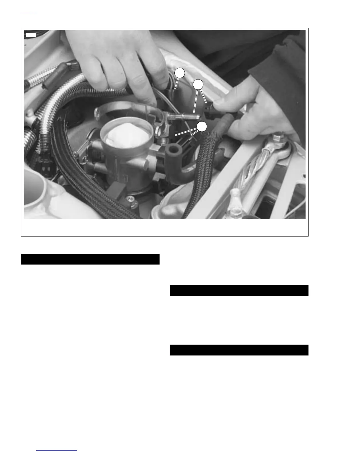
18. See Figure 3-15. Connect throttle position sensor (2)
[88].
19. Connect fuel injector leads (3) [84 & 85].
20. Connect fuel line.
21. Install throttle body velocity stack (tighten).
22. Install airbox assembly and intake cover and tighten fas-
teners to 84-120 in-lbs (9.5-13.6 Nm).
23. Install rear belt and idler pulley. See 1.10 DRIVE BELT
and 2.13 REAR BRAKE MASTER CYLINDER.
24. Install left side rider footrest and support plate and
tighten fasteners to 120-144 in lbs (13.56-16.27 Nm).
25. Install sprocket cover and tighten fasteners and washers
to 12-36 in-lbs (1-4 Nm).
26. Install chin fairing. See 2.34 CHIN FAIRING.
27. Install air scoops, right and left sides. See 2.36 AIR
SCOOPS.
28. Connect fuel pump.
NOTE
The connection for fuel pump is just above the pump located
at the rear of the fuel tank on the left side of the vehicle.
11WARNING1WARNING
Always connect positive battery cable first. If the positive
cable should contact ground with the negative cable
installed, the resulting sparks may cause a battery explo-
sion which could result in death or serious injury.
29. Connect negative ground cable to battery and install seat
(tighten).
11WARNING1WARNING
Pull up on seat to verify that it is properly secured, front
and rear. A loose seat may shift during vehicle operation
and startle the rider, possibly causing loss of vehicle
control resulting in death or serious injury.
Figure 3-15. Fuel Line and DDFI Electrical Connections
8707
1. Fuel line connection
2. Connection for throttle position sensor [88]
3. Connections for fuel injectors [84 & 85]
2
1
3