2003 Buell XB9S: Engine 3-59
HOME
PUSH ROD COVER INSTALLATION
NOTE
Push rod covers must be installed prior to installing cylinder
heads.
1. See Figure 3-86. Install push rod covers.
a. Install new o-rings (2) on top of each push rod cover
(3).
b. Install new push rod cover gasket (5) onto bottom of
each push rod cover.
c. Install each push rod cover assembly and start the
fasteners (4) securing the bottom of each cover to
the crankcase.
d. Tighten fasteners to 30-40 in lbs (3.4-4.5 Nm).
2. Refer to Ta ble 3-21. Identify push rod color coding,
length and respective push rod positions in engine. Place
intake and exhaust push rods onto seat at top of tappet.
CAUTION
After head(s) have been installed do not turn engine over
until both push rods can be turned with fingers. Other-
wise, damage to push rods or rocker arms may result.
Figure 3-85. Push Rod Locations
Table 3-21. Push Rod Selection
POSITION
COLOR
CODES
LENGTH PART NO.
Exhaust 1 Band-
Pink/Purple
10.780 in.
(274.320 mm)
17908-02
Intake 1 Band-
Orange/Brown
10.726 in.
(272.948 mm)
17909-02
8682ß
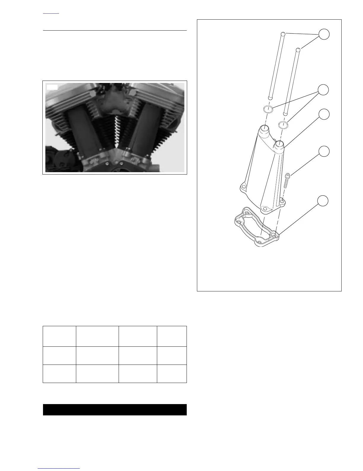
Figure 3-86. Push Rods and Push Rod Cover Assembly
b1092x3x
1
3
4
1. Push rod (2)
2. O-ring (2)
3. Push rod cover
4. Screws (4)
5. Push rod cover gasket
2
5
 Loading...


