11
6.2.1 Cleaning the nozzle
• Wipethenozzlewithaclothtoremoveslightexternaldirt.
• Toremoveblockagesinsertadrillbit,needleorwireofsuitablediameterintothe
nozzleorice.
Instubborncasesreplacethenozzle(seeSection6.3).
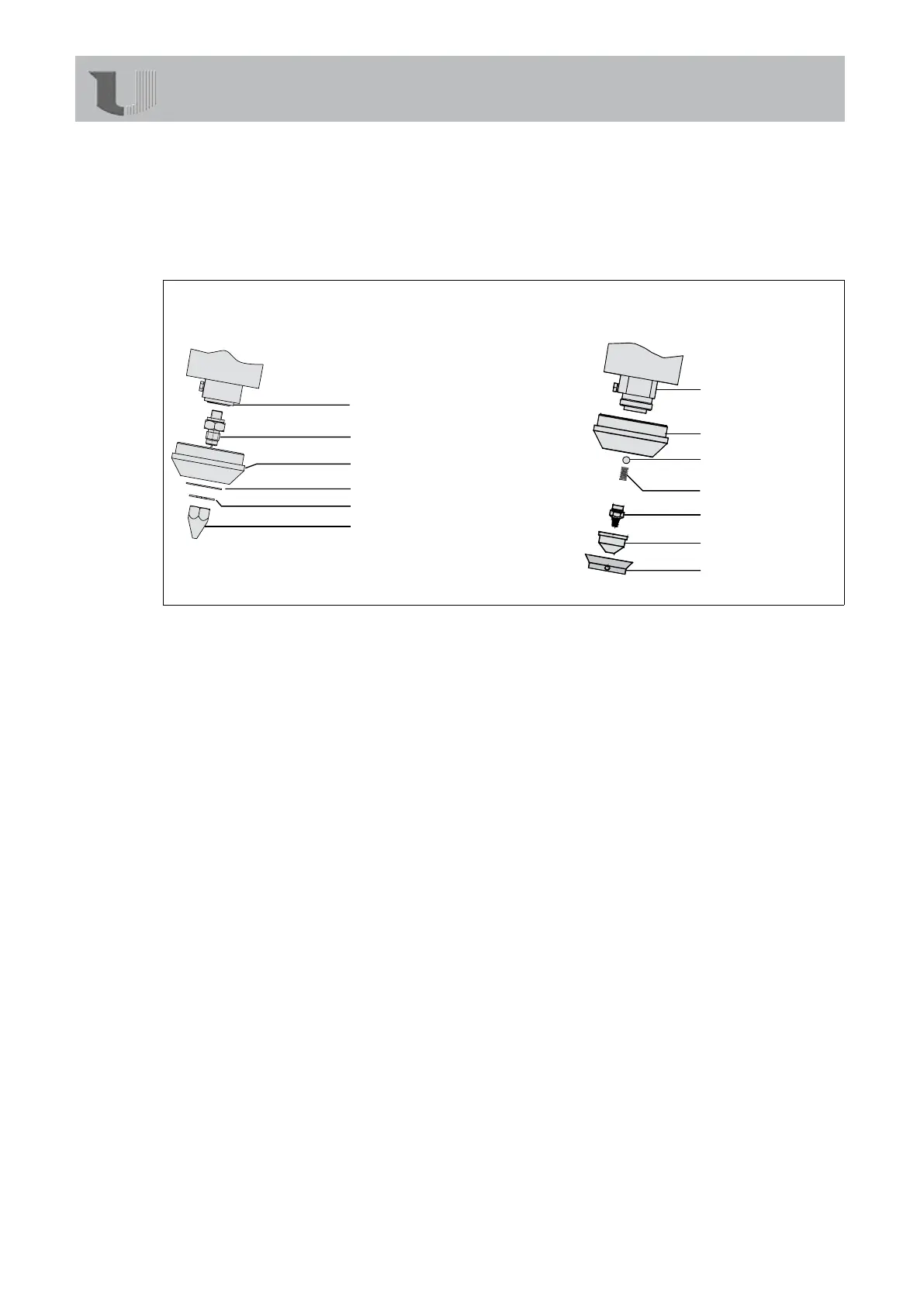
6.3 Nozzle systems
Valve seat (A6)
Nozzle foot (A5)
Protection cap (A4)
Washer (A3)
Locking ring (A2)
Cone nozzle (A1)
Nozzle block (B7)
Protection cap (B6)
Ball (B5)
Pressure spring (B4)
Swirl nozzle (B3)
Air cap (B2)
Cap ring (B1)
Fig 6.3/1: Nozzle systems in detail
6.3.1 Replacing the cone nozzle (HB 710)
Tools needed • 2open-endspannerssize19
• 1Seegercirclipringpliers
1. Disconnectthecompressedairsupply.
2. Letthedeviceheatupthoroughly.
3. Securethenozzlefoot(A5)andunscrewtheconenozzle(A1).
4. Screwonthenewconenozzle(A1)byhandrstandallowtoheatupfor2minutes.
5. Re-securethenozzlefoot(A5).Tightenthenewconenozzle(A1)withoutusingforce.
6. Assembletheremainingpartsinreverseorder.
6.3.2 Replacing the nozzle end (HB 710)
Tools needed • 2open-endspannerssize19
• 1open-endspannersize36orpipewrench
• 1Seegercirclipringpliers
Theremustbenomeltatallinthetankwhenthenozzleendisreplaced.
Thereforedischargethemeltcompletely,e.g.intoacollectingvessel.
1. First,proceedasdescribedinchapter6.3.1uptoPoint3(dismantlingthenozzle).
2. Removethelockingring(A2).
3. Removethewasher(A3)andtheprotectioncap(A4).
4. Securethevalveseat(A6)withtheopen-endspannersize36orthepipewrench.
Unscrewthenozzlefoot(A5).
5. Screwonthenewnozzlefoothandtight.Nowtightenlightly(withoutusingforce)with
theopen-endspanner.
6. Assembletheremainingpartsinreverseorder.
Servicing/maintenance