20
•Thoroughlycleanthelowerchamber.
•Assemble the ceramic elements back
intothelowerchamberinreverseorder
– back (5), both sides (3 and 4) and
boom(2and1).
5. Cleaning of fume exhaust tubes of
boiler.
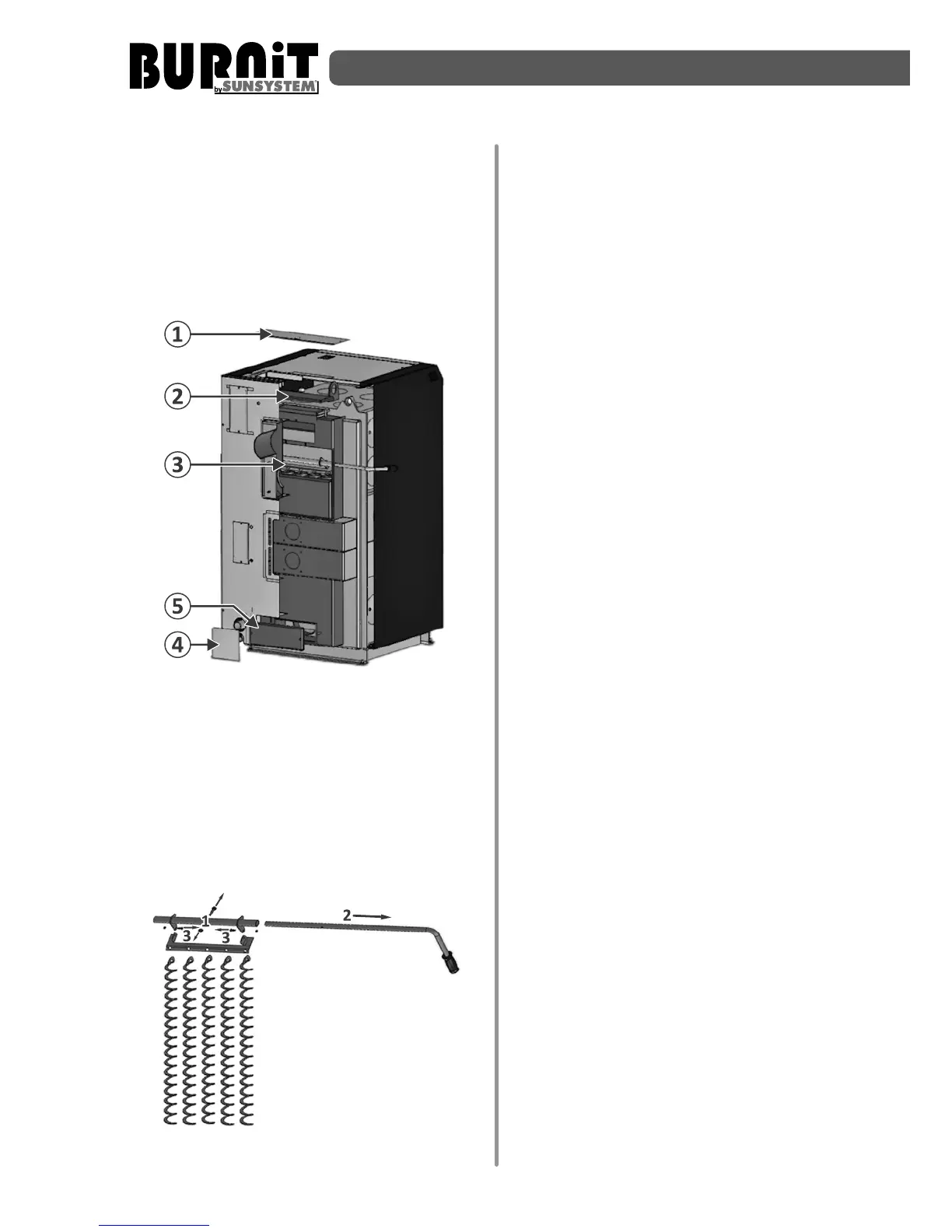
Diagram 16
•Uppercleaningopeningislocatedontop
ofboiler.Itisprotectedbytwocovers.
Unscrewthetwowingnuts.Disassemble
the decorave lid of upper cleaning
openingonboilercasing(1)
•Unscrewthetwowingnuts.Disassemble
the lid of upper cleaning opening on
boilerbody(2)
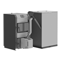
Diagram 17
•Remove the cleaning system (diagram
17) using a wrench S13 and S7.
Thoroughly clean fume exhaust tubes
(3)ofsootdeposits.Usethebrushfrom
equipmentdelivery.
•Lowercleaningopeningislocatedbehind
theboiler,lowdown.It isprotectedby
twocovers.Unscrewthetwowingnuts.
Disassemblethedecoravelidoflower
cleaningopeningonboilercasing(4)
•Lower cleaning opening. Unscrew
the two wing nuts. Disassemble the
decoravelidoflowercleaningopening
onboilercasing(5).
•Remove soot accumulaon aer the
cleaningoffumeexhausttubes
•Assemble the lid of upper cleaning
opening on boiler body (2). Make sure
thelidisplacedcorrectlyandght.
•Assemble the decorave lid of upper
cleaningopeningonboilercasing(1).
•Assemble the lid of lower cleaning
opening on boiler body (5). Make sure
thelidisplacedcorrectlyandght.
•Assemble the decorave lid of lower
cleaningopeningonboilercasing(4).
9.4. Important recommendaons for
long-lasngandcorrectoperaonofthe
boiler
•Pleaseperformperiodicmaintenanceof
the boiler as described in instrucons,
secon9.2.
•Theallowedmoisturecontentofthefuel
usedmustnotexceed15%÷20%.
•Gas emission in the combuson
chambermayresultintheformaonof
tar and condensate (acids). Therefore,
a mixing valve must be installed and it
mustbeadjustedsothattheminimum
temperature of the water returning in
the boiler is 65°С. This extends the life
spanoftheboileranditswarranty.The
operang temperature of the water in