107 of 166
6.3.4.2 PLC inputs
Some PLC inputs at the I/O interface or on the optional Fieldbuses can be configured with various
functions. Section 4.3.2 “PLC I/O signals” on page 23 contains a full list of the I/O interface assignments
including a summary of which pins can be assigned a configurable function.
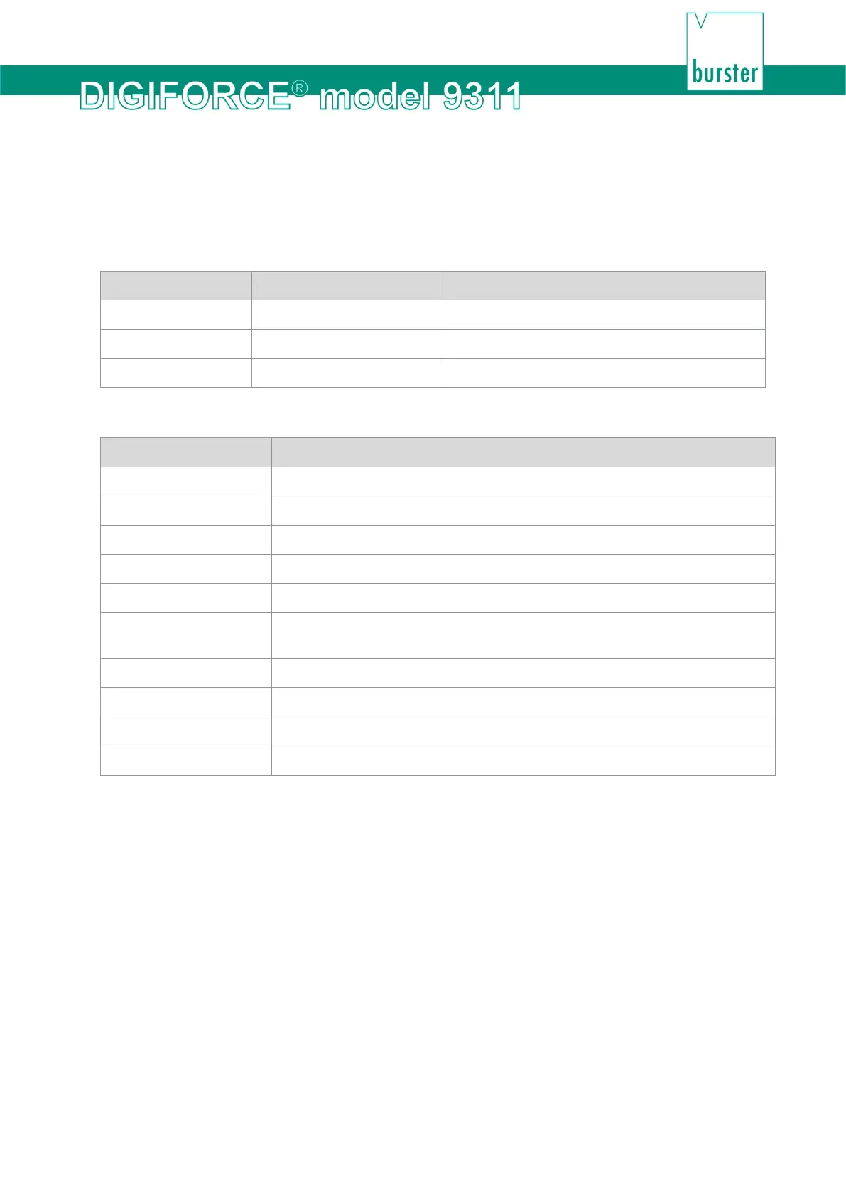
The following inputs can be configured by the user:
Input Default assignment Meaning
Input 1 (Pin 4) IN_TARE_X Tare the X-channel
Input 2 (Pin 5) IN_RES_STAT Reset the statistics
Input 3 (Pin 6) IN_STEST Run the sensor test
You can assign the following signals to the inputs:
Signal Description
IN_TARE_X Tare the X-channel
IN_TARE_Y Tare the Y-channel
IN_TARE_X+Y Tare the X-channel and Y-channel
IN_RES_STAT Reset the statistics
IN_STEST Run the sensor test
IN_TEST_OP Switch to Graphical test operation (measurement / evaluation without
counter)
IN_ACK Acknowledgement function – acknowledgement of OK and NOK evaluations
IN_ACK_OK Acknowledgement function – acknowledgement of OK evaluations
IN_ACK_NOK Acknowledgement function – acknowledgement of NOK evaluations
IN_ACK_ERROR Acknowledgement of errors/faults (when "OUT_ERROR" = 1)*
*If the DIGIFORCE
®
9311 has a permanent error, the "OUT_ERROR" output cannot be reset by
acknowledging the error.
 Loading...