145 of 166
10.2.2 Measurement with measurement-data logging
The DigiControl PLUS PC software for the DIGIFORCE
®
9311 provides the option for automatic data
logging at the end of a measurement. When data logging is enabled, the "OUT_READY" signal, which
indicates that the DIGIFORCE
®
9311 is in standby and ready to perform another measurement, is not set
until data transmission is complete. The time taken for data logging depends on the choice of
communication interface and on the size of the measurement curve. The time length for data logging
shown in the signal timing diagram is the time typically taken when the Ethernet port is used.
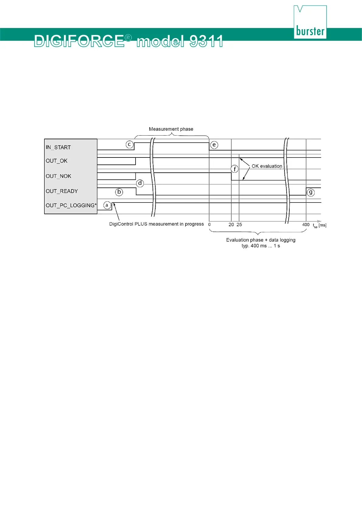
Diagram 88: With measurement-data logging
*You can define a configurable PLC output for the signal "OUT_PC_LOGGING".
Cycle
a. DigiControl PLUS (PC software) sets the signal "OUT_PC_LOGGING" to 1 when
measurement mode starts.
b. The controller (PLC) checks whether the DIGIFORCE
®
9311 is ready
("OUT_READY" = 1).
c. The PLC starts the measurement with "IN_START" = 1.
d. During the measurement phase the DIGIFORCE
®
9311 sets the signals "OUT_OK"
and "OUT_NOK" to 1 and the signal "OUT_READY" to 0.
e. The PLC stops the measurement by resetting the signal "IN_START" to 0.
f. The DIGIFORCE
®
9311 updates the result during the evaluation phase:
"OUT_OK" = 1 and "OUT_NOK" = 0: measurement OK
"OUT_OK" = 0 and "OUT_NOK" = 1: measurement NOK
g. At the end of the evaluation phase, the DIGIFORCE
®
9311 sets the signal
"OUT_READY" to 1 (in standby).
Tip
To optimize cycle times, the PLC can retrieve the OK/NOK evaluation immediately after the measurement
rather than waiting for the READY signal, which it can check before the next measurement.
 Loading...