143 of 166
10.1.2 Changing the measurement program with program
acknowledgement
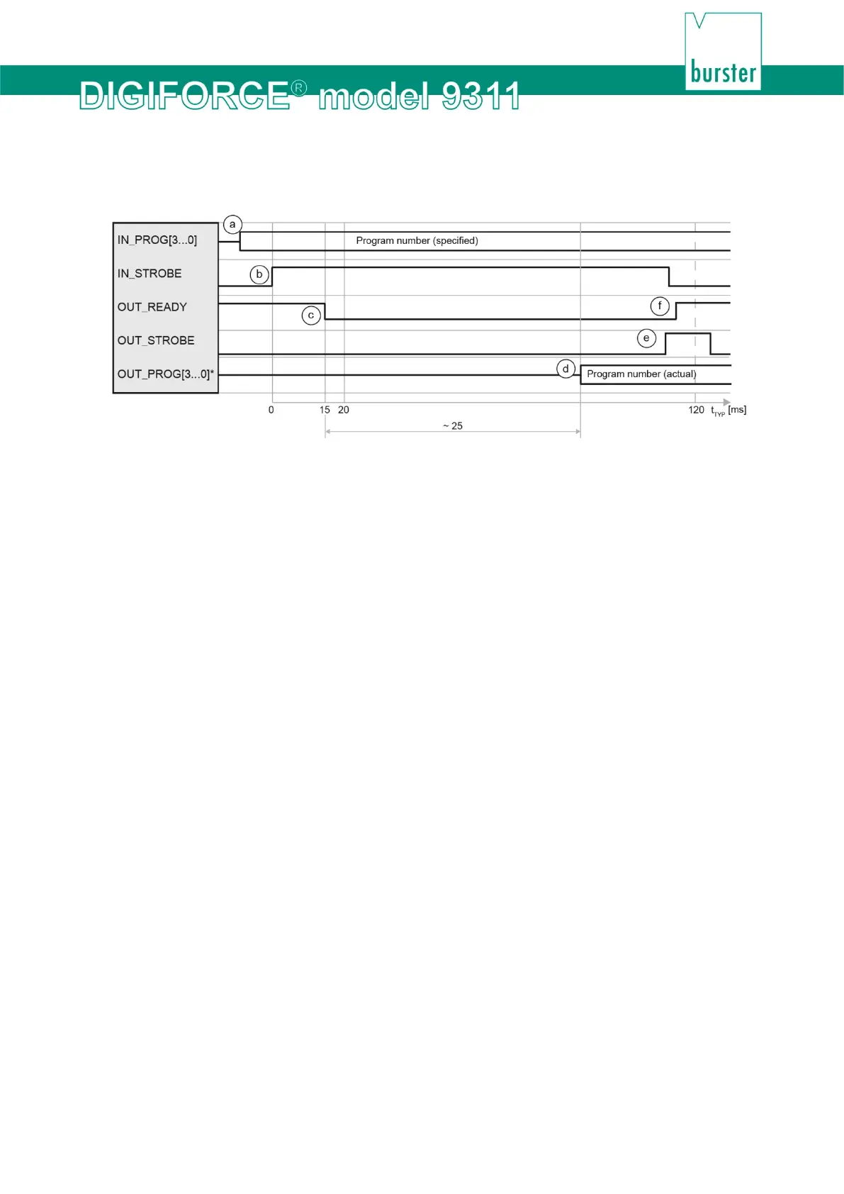
Diagram 86: Changing the measurement program with program acknowledgement
*You can define a configurable PLC output for the signals "OUT_PROG[3...0]".
Cycle
a. The controller applies the required program number (binary encoded) to the address
inputs and checks whether the DIGIFORCE
®
9311 is ready
("OUT_READY" =1).
b. The controller sends the strobe signal ("IN_STROBE") in order to transfer the program
number.
c. On detecting the strobe signal, the DIGIFORCE
®
9311 sets the READY signal to "0".
d. The DIGIFORCE
®
9311 updates the program number echoed at the address outputs
("OUT_PROG[3...0]"*) with the selected program.
e. At the end of the program-selection cycle, the DIGIFORCE
®
9311 enables the output
signal "OUT_STROBE". On detecting the "OUT_STROBE" signal from the 9311, the
PLC can receive and validate the program number "OUT_PROG[3...0]"*
acknowledged by the DIGIFORCE
®
9311. Then the PLC can reset the initiating control
signal "IN_STROBE" ("IN_STROBE" = 0).
f. After “IN_STROBE” has been reset, the DIGIFORCE
® 9311 sets the READY signal
and resets “OUT_STROBE”. Only then the cycle is completed.
Tip
You can connect unused address inputs ("IN_PROG[]") permanently to Ground potential.
Note: This applies only to all unused inputs. Otherwise outputs can be triggered incorrectly if extreme
interference fields exist or there are large fluctuations in the PLC supply potential with respect to
Ground potential.
 Loading...