EN
13
7 Start-up
TheunitmayonlybeperformedbyBWTservicestaortrainedper-
sonnel.
Pleasefollowtheoperatinginstructionsfortheboosterpump,lteretc.
Start-up can be initiated when the system is fully connected:
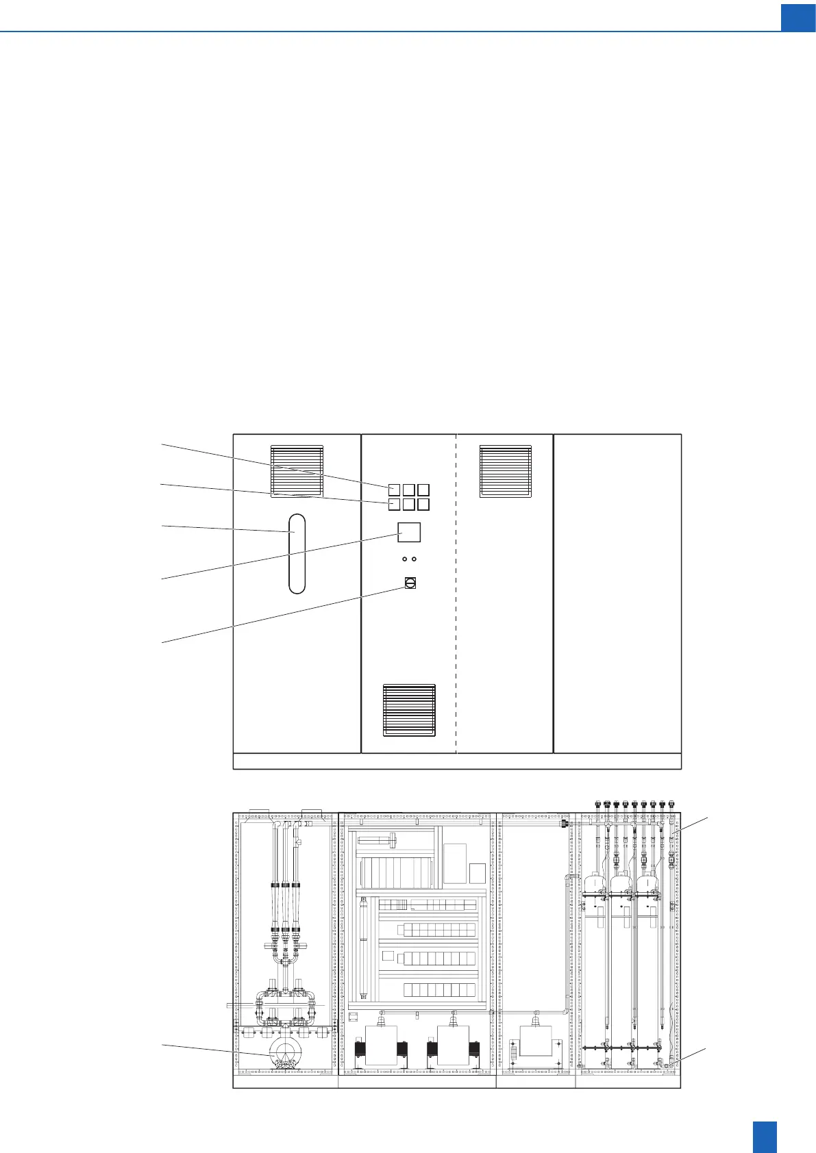
1. Close drain valve (C) for cooling water (bottom right, rear of unit).
2. Check power supply breaker F1 (see terminal diagram).
3. Check supply voltage.
4. Check the control and safety connections of the control point.
5. Switch on main switch (14).
– Display on TP (touch panel): Bewazon ozone device ready.
– Set the time; see the operation instructions for directions.
– Acknowledge maintenance notes.
– Check: Power supply lamp on
– Check: Fault signal lamp Open the door to trigger the door switch
fault/emergency stop.
6. Set ozone generation level to zero.
7. Enable ozone generation.
8. Adjustairowatthe(external)injectorusingtheairowmeter(2).
9. SwitchdryerontheTPandcheckairow.
10. If necessary, wait for cooling water to drain.
11. Measure the dew point of both dryers at the connection after the
ozone tubes (A).
12. Check pipes for leaks.
13. Check the thermostat settings for the dryer and cooling water.
14. Verify basic settings of all operating parameters.
15. Perform blower test on both dryers:
– (Request via TP, see chapter 8.6 “Operation”).
–Checktheairowandrotationdirectionoftheregenerationblower
(3).
– Measure heating current of both heaters.
– Measure blower current consumption.
16. Set ozone generation to 1. After the pre-operation purge, check the
current consumption of the high voltage transformer at the ammeter.
Compare with test log. Multi-circuit systems: The values indicated on
the voltmeter and ammeter (7, 8) only relate to the circuit displayed
on the TP below them (9).
17. Check stages 2 to 14/16 (PVC/VA) with the same process as stage 1.
18. Disable generation release, the system is ready after the post-
operation purge.
Bewazon 350 3 circuit system with stainless steel ozone generators
14
2
9
7
8
3
C
A