EN
25
Example: Variable mixing
Preset: The customer preset corresponds to the conventional mixing
operation,regardlessoftheozoneoutput,i.e.airowo=>mixingo=>
outputsignal=4mAairowon=>mixingon=>outputsignal=20mA
The air input for ozone mixing should be set on the injector according
to the current ozone output. That means that the ozone mixing should
beoperatedas variablemixing(see below).Todo so,theinjector's
pressure booster pump is run via a frequency converter, which in turn is
actuated by the analogue output signal. This means that less air is input,
for example, when operating at the medium ozone level, and the current
consumptionofthemixeralsodecreases,oftenquitesignicantly.
For this mode of operation, the external injector must be suitable for
operationwithavariableairow.Thesuitabilityforthismodeofope-
ration must be checked ahead of time if necessary.
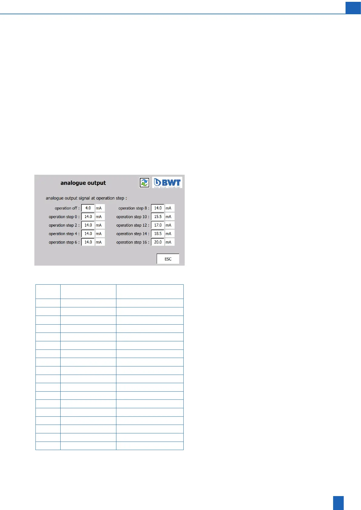
Setting variable mixing
Theanalogueoutputsignalisconguredatthefactorysothatexternal
mixingcanbeoperatedconventionallyatrst.
That means:
-Ozonedeviceo=>signal=4mA=>boosterpumpo.
- Ozone device on, with level 0 to 16 => signal = 20 mA => booster
pump on with 100% pump capacity.
Whenoperatingatlevel0(signal=20mA),themixingmustrstbe
set on the corresponding valves on the injector so that it draws 100%
ofthenominalairowoftheozonedevice.
Once the valves are set this way, they must not be changed afterwards.
Next, you must determine – likewise during operation at level 0 – how
much the air ow can be reduced via the analogue signal without
causingthe airow tobecome unstableor tobe interrupted.To do
so, you must gradually decrease the value of the signal for “Operation
level0”untilallofthesignalvaluesfortheentirecontrollableairow
range are determined.
Stableoperationshouldbepossiblewithnominalairowreducedto
50 to 60%.
If, for example, stable operation is achieved at 50% of the nominal air
owwithasignalof14.0mA,thisairowcanbesetuptolevel8(which
corresponds to 50% of the ozone production capacity).
Operati-
on/level
Set
output signal (mA)
1)
Resulting
airow,approx.(%)
OFF 4.0 0.0
0 14.0 50.0
1 – 50.0
2 14.0 50.0
3 – 50.0
4 14.0 50.0
5 – 50.0
6 14.0 50.0
7 – 50.0
8 14.0 50.0
9 – 56.3
10 15.5 62.5
11 – 68.8
12 17.0 75.0
13 – 81.3
14 18.5 87.5
15 – 93.8
16 20.0 100.0
Theunit isoperated upto level8 with50% of thenominal airow.
Athigherlevels,theairowincreasesgraduallyandcontinuallywith
the ozone output.
Settings must be made according to the adjacent table.
The adjustable range between 50% and 100% is evenly distributed
overthecorrespondingrangeoflevels,i.e.abovelevel8,theairow
should increase by approx. 6.25% per level (50% of the control range
divided into 8 levels = 6.25% per step)
1) The output signal for odd levels is determined by the PLC as the
mean value of the setting for the level above and below it.