2021/03 - Indice de révision : B Code : 29740 TRAITEMENT DE L'EAU
36/88
4. INSTALLATION
Thedeviceshouldbeinstalledinthepoolplantroom,protectedfromtheweatherandthesun.
4.1 Hydraulic connections
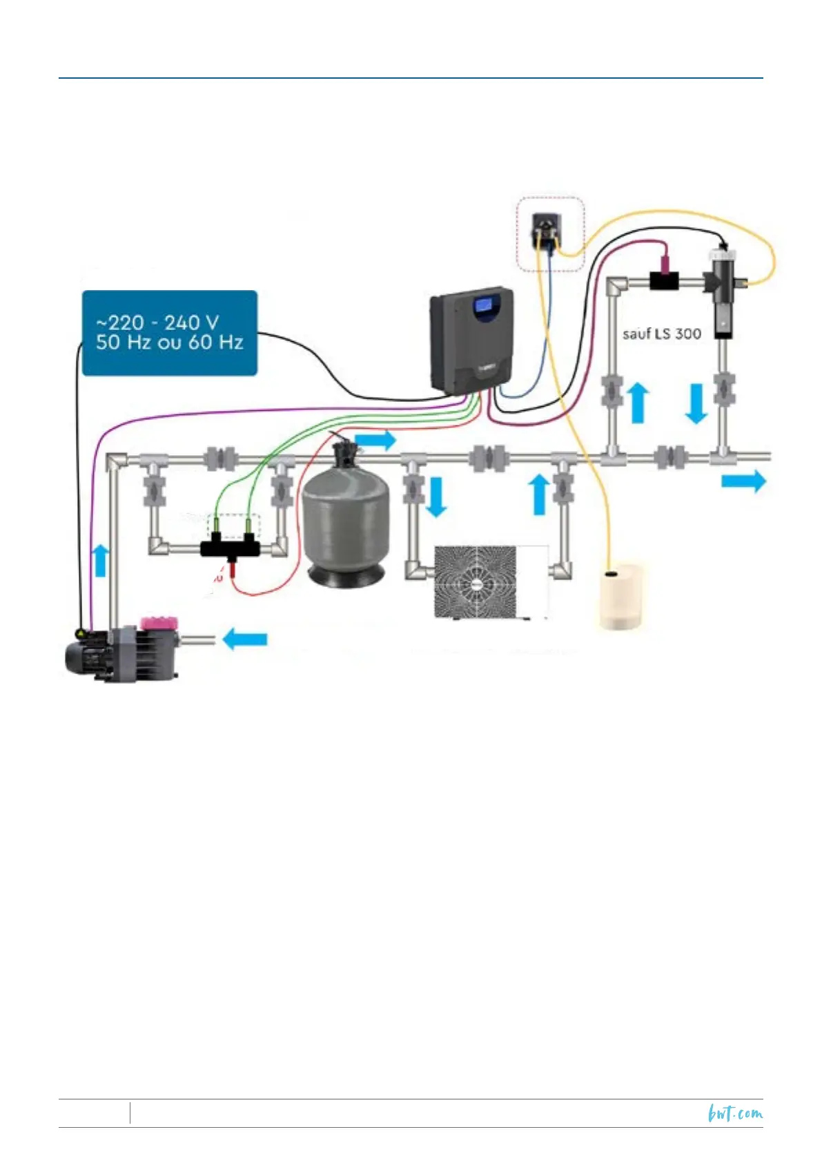
Connectionsshouldbemadeaccordingtothefollowingdiagram:
Tothepool
Fromthepool
pH and
Redox
sensors
(option)
Flowswitch
(option)
Powersupply
Water temp
sensor
Heating device
!
Important:Whenchoosingthelocationsofthecontrolpanelandthecell,andbeforestartingwork,
makesurethattheelectricalcablethatwillconnectthepanelandthecellislongenoughto
make the connection;
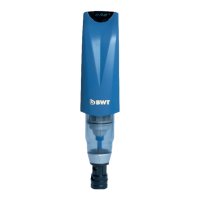
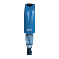
4.1.1 Mounting the cell
• InthecaseofthePROAandPROLS65and200models(equippedwithagassensor),thecell
mustbeinstalledverticallyandatahighpointsothatthegassensorlocatedonthecellpower
supplysidecanrunproperly.Ifitisnotpossibletoinstallthecellverticallyatahighpoint,aow-switch
kitmustbeinstalled.
• InthecaseofthePROLS300model,andothermodelsttedwiththeFlow-switchoption,thereareno
constraintsregardingtheorientationofthecell,onlythatoftheow-switch(see4.1.5).
• Respectthefollowingdirectionofow:watershouldenterthecellfromthetop,owpastthe
electrodesandexitfromthebottom.
4.1.2 Mounting the temperature sensor
• Mountthesensorhousingonaby-passloop(50or63mm)locatedbetweenthelterandtheheating
device(seethehydraulicinstallationdiagram).Thehousingmustbeorienteddownwardssothatthe
sensorsarealwaysinwaterandtheirreadingsarerepresentativeofthecurrentpoolwatervalues.The
housingmustbeinstalledonahorizontalsectionoftheby-passloop,orientedsothatthesidewith2
holespointsup(optionalpHandRedoxsensors),andthesidewithoneholefacesdown(temperature
sensor).Screwthetemperaturesensorsdirectlyintothedownwardfacing1.2‘‘tappedorice.