Operating instructions
EVS17/07-DS/IU und EVS17/12-DS/IU
Trautmann GmbH & Co. KG -ApparatebauCALIRA
Lerchenfeldstr. 9 87600 Kaufbeuren Tel.08341/9764-0 Fax 08341/67806
Internet: http://www.calira.de Email: info@calira.de
34
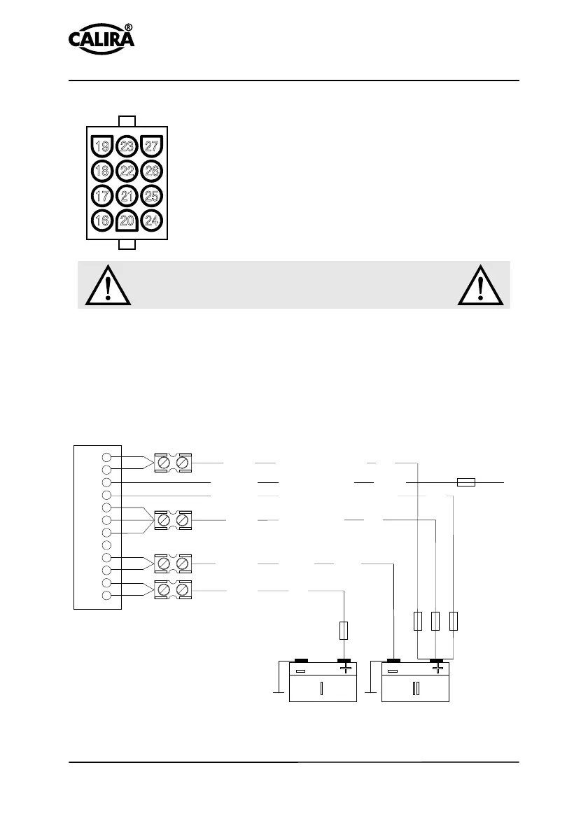
Connecting a 12-pole plug connector
The illustration (Fig. 9) shows the contacts available in the
12-pole plug connector. Connect the 12-pole plug conne-
ctor to the generator, starter battery and supply battery in
accordance with the connecting diagram.
Make sure that the contact pins engage securely with the
plug connector! Loose contact pins can lead to malfunc-
tions or short-circuiting.
Position the fuses close to the positive poles of the batteries and to the D+ of the
generator.
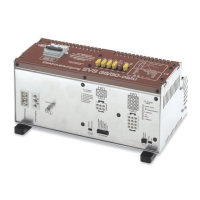
Insert the plug connector into the socket provided on the device (Fig. 2). The
plug connectors can only be inserted and locked into the correct socket and in
the correct position. Make sure that the locking engages securely. To withdraw
the connector plug, the locking must be released by pressing the two wings
together.
Fig. 9: 12-pole connector
Fig. 10: Connecting diagram 12-pole plug connector
The fuses must be positioned close to
the positive poles of the batteries!
26
22
18
25
24
20
21
17
16
27
23
19
16
17
18
19
20
21
22
23
24
25
26
27
2A
2A
40A
25A
40A
6mm
2
+ Supply
6mm
2
red
red
red
red
0,75mm
2
D Generator+
0,75mm
2
B+ Measuring cable/Test
4mm
2
+ Charging current
4mm
2
minus blue
brown
++
lll
__
Battery 12 V
(supply)
Battery 12 V
(start)
The fuses serve to protect the circuits.
Do not use higher fuse values: fire hazard!
 Loading...