9
Proprietary Information: Not for use or disclosure except by written agreement with Calix.
© Calix. All Rights Reserved.
The E7-2 power inputs (A/B), ground, alarm I/O, Craft management, and BITS timing
interfaces are located on the rear of the E7-2 shelf. The E7-2 rear panel also has four RJ-21
copper interface connectors.
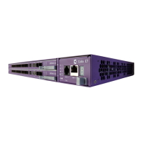
Calix E7-2 cards
The Calix E7-2 is equipped with two universal line card slots, supporting a flexible array of
high capacity line cards, including:
Fiber access service line cards: Calix E7-2 fiber cards provide optical ports for front
access termination.
Copper access service line cards: Calix E7-2 copper cards (e.g., VDSL2) terminate on
the E7-2 rear panel.
All E7-2 line cards use pluggable transceiver modules for optical and copper-based interfaces,
including industry standard SFP, SFP+ and XFP modules. Each port on each card has an
LED to indicate an established link and data traffic activity. For detailed information on the
E7-2 line cards, see the Calix E7 User Guide.
An E7 'blank' card (equipped with no electronics) ships with every E7-2 shelf. The blank
card plugs into either of the two universal slots and is used to maintain emissions and
facilitate proper airflow in E7-2 systems with only one line card. Whenever an E7-2 shelf
operates with only one line card, a blank card must be installed in the other slot.