58
Proprietary Information: Not for use or disclosure except by written agreement with Calix.
© Calix. All Rights Reserved.
RJ-21 Pin Assignments
This topic provides the RJ-21 connector pin assignments. To wire the Calix E7-2 for DSx
services (e.g., VDSL2/POTS), use 25-pair cables with an RJ-21 male connector. Calix
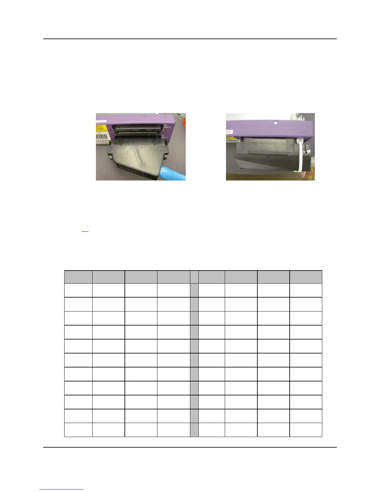
recommends that the RJ-21 connector on the 25-pair cables use a 110 degree exit or 90
degree exit (at pins 1 and 26).
110-degree exit 90-degree exit
For instructions on installing an RJ-21 connector, see Connecting to the Subscriber Interfaces (on
page 44).
Pin assignments
The E7-2 standard RJ-21 pinout assignments follow:
Pin Color Tip/Ring Circuit
Pin Color Tip/Ring Circuit
1 BL/WH Ring 1
26 WH/BL Tip 1
2 OR/WH Ring 2
27 WH/OR Tip 2
3 GN/WH Ring 3
28 WH/GN Tip 3
4 BR/WH Ring 4
29 WH/BR Tip 4
5 SL/WH Ring 5
30 WH/SL Tip 5
6 BL/RD Ring 6
31 RD/BL Tip 6
7 OR/RD Ring 7
32 RD/OR Tip 7
8 GN/RD Ring 8
33 RD/GN Tip 8
9 BR/RD Ring 9
34 RD/BR Tip 9
10 SL/RD Ring 10
35 RD/SL Tip 10
11 BL/BK Ring 11
36 BK/BL Tip 11