Widgets & Icons
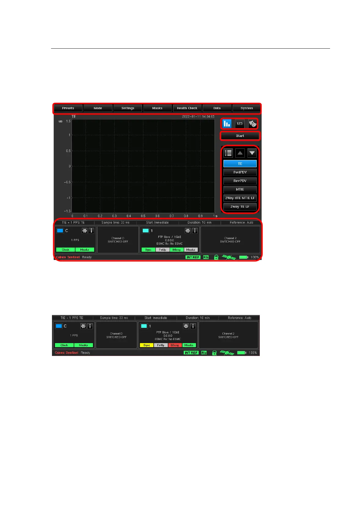
A Widget is displayed at the bottom of the screen for each of the input modules and corresponding channels.
Each input module will feature one or more channel. Each Widget is named based on the corresponding symbol
on the Side panel of the Sentinel. For the display below one Clock module is installed with channels C & D, two
Packet modules are installed represented by channels 1 & 2.
A series of status icons are available on the bottom status bar of Sentinel indicating the state of various
modules/features of the Sentinel unit.
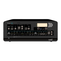
8.1 Measurement channels
Each populated measurement channel has an associated widget to indicate the status and configuration of the
channel and to allow quick access to the channel settings. Each channel has a specific colour in the top left which
corresponds to the graph for that channel
The coloured button in the top left of each Widget for a channel can be used to bring the channel to the
foreground of the displayed measurements (Bring to top) or to hide it from the measurement screen and mask
test (Hide). When hidden the background of the input signal data will be greyed out and the coloured button can
be used to re-enable display of the channel (Show).
Loss of signal LEDs and Mask pass / fail results are displayed at the bottom of the widget.
A green LED indicates that the associated clock signal, OTA lock or PTP/NTP message is present or that the mask
has passed.
A red LED indicates that the associated clock signal, OTA lock or PTP/NTP message is absent or that the mask
has failed.
A yellow LED indicates that the associated clock signal, OTA lock or PTP/NTP message has been absent but is
now present again.
A grey LED indicates that the associated PTP message is not relevant (e.g. Follow Up when running in 1-step
mode) or the test has not run long enough to validate the mask.