20 ARGO Digital Broadcast IP Production Console
Control Surfaces
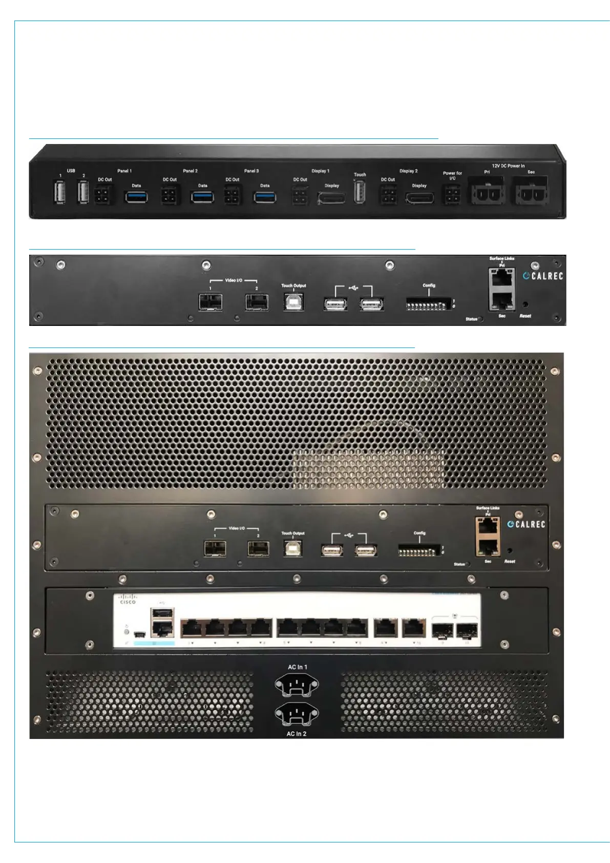
FIG 1 - UN6539 SECTION PROCESSOR FRONT VIEW AS SEEN FROM FRONT OF CONSOLE
FIG 2 - UN6539 SECTION PROCESSOR REAR VIEW AS SEEN FROM BACK OF CONSOLE
FIG 3 - UN6539 SECTION PROCESSOR LOCATED IN REAR OF A CONSOLE SECTION
Component Placement
Fig 3. above shows an Argo console
section seen from the rear, the
components are placed as follows:
2 x ZN6578 Surface PSU modules side
by side at the bottom (behind vent panel),
2 x IEC Mains AC Inlets in first section
between the ZN6578 PSU modules.
1 x 491-329 Cisco GB Ethernet switch in
the middle.
1 x UN6539 Section Processor at the top.
Vent panel above section processor.
Note: the Cisco GBE switch is powered
from the Power for I/O connector.