Pag.
- Manual code:
119DV74
ver.
01/2011
© CAME cancelli automatici s.p.a. - The data and information reported in this installation manual are susceptible to change at any time and without obligation on CAME cancelli automatici s.p.a. to notify users.
ENGLISH
The following applications are only examples, in that the space available for fixing the operator and accessories varies depen-
ding on the dimensions. It is thus up to the installer to choose the most suitable solution.
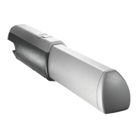
5.5 Mounting
Apply the fixing plate to the post using the tail bracket, making sure that the values , A and B (tab. 3), are met between the hinge axis
and the bracket’s centre hole. The tail bracket is fitted with further holes to allow for variation of the gate’s opening angle.
N.B.: increasing measurement B reduces the opening angle and thus the peripheral speed and increases the motor thrust on the
gate leaf. Increasing measurement A increases the opening angle and thus the peripheral speed and reduces the motior thrust on
the gate leaf.
Pillar
Hinge
Leaf - closed
position
Anchoring plate
Back bracket
Bushing
Back swivel-
joint
Tab. 3
Gate leaves < 3 m
Opening
A
mm
B
mm
C <
mm
E
mm
90° 130 130 60 720
120° 130 110 50 720
Gate leaves < 5 m
90°
200 200
120 920
120°
200
140 70 920
 Loading...