4 01/2015
© CAME S.p.A. - The data and information in this manual may be changed at any time and CAME S.p.A. is under no obligation to inform users of said changes
6 ZF1 control board
6.2 Description
Designed and built entirely by CAME S.p.A.
Power supply 230 V AC on terminals L1 and L2. The board is
protected by a 5 A fuse, while the low voltage accessories (24 V)
are protected by a 3.15 A fuse.
Warning! The overall power of the 24 V accessories must not
exceed 20 W.
All connections are protected by quick fuses, see table.
The board manages and controls the following features:
- automatic closing;
- hold-to-run action.
The available command modes are:
- opening/closing;
- total stop.
The photocells, after detecting an obstacle, may trigger:
- the reopening of the closing gate;
- a total stop.
Specific trimmers regulate:
- the working time for automatic closing;
- the delayed closing time of gearmotor 2;
- the working time.
You can also connect:
- a 12 V electric lock;
- a gate-open signal lamp.
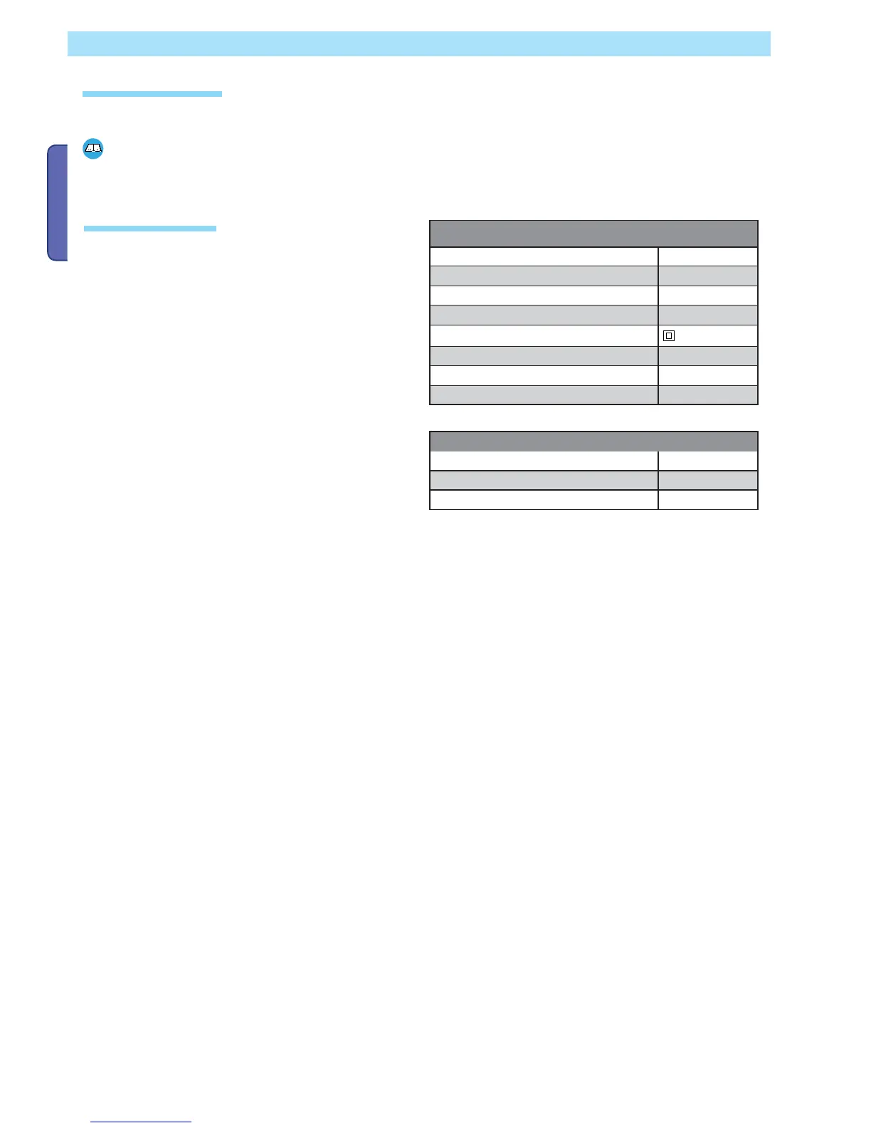
FUSE TABLE
to protect: fuses for:
Electronic board (line)
A 5
Command devices and accessories 3.15A
TECHNICAL DATA
Power supply
230 V - 50/60 Hz
Maximum allowed power load 320 W
Power draw when idle 40 mA
Maximum power for 24 V accessories 20W
Circuit insulation class
Container material ABS
Container protection rating IP54
Working temperature - 20 / +55°C
The ZF1 control board is made for commanding operators for one- or two-leaf swing gates.
Any installation and use other than that specified in this manual is forbidden.
6.1 Intended use
 Loading...