4 01/2015
© CAME S.p.A. - The data and information in this manual may be changed at any time and CAME S.p.A. is under no obligation to inform users of said changes
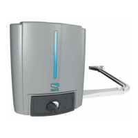
Insert the operator into the post-mounted bracket; match the four holes and fasten it using the two issued M8x90 screws and M8
nuts (4).
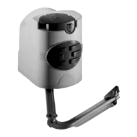
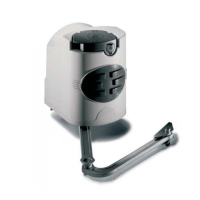
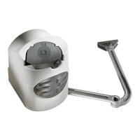
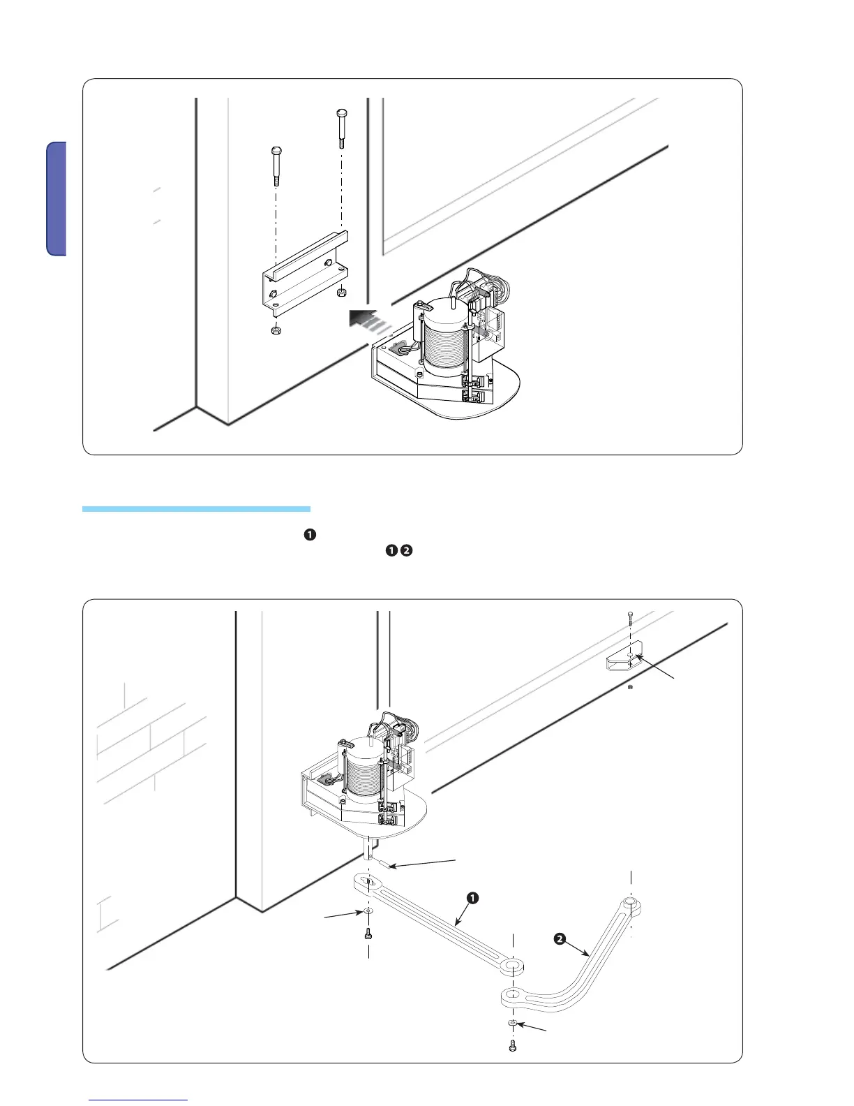
- Insert the Ø 10x40 pin and the straight arm into the gearmotor shaft and fasten it using an M10x14 screw and Ø 10x35 washer.
Lubricate the straight arm pin. Join and fasten the two arms
with the M6x10 and the Ø 6x24 washer. Release the gearmotor
and fasten the curved arm to bracket A using the M12x40 screw and the M12 nut. Make sure the arm slides freely.
5.7 Applying the articulated arm
Bracket A
Pin
ø 10x40
 Loading...